page 6
INSTALLATION & INITIAL SETUP PTU-D46 User’s Manual (v2.14.0)
3.3 Initial Installation and Connections
If you have the power source and RS-232 cables described in Sections 3.1 and 3.2, you are
ready to connect the pan-tilt unit components together and test its operation. We suggest that you
do not mount your payload (e.g., camera) until the initial installation is completed and tested.
1. Mount the Pan-Tilt Unit using standard #1/4-20 screws. The unit has two front and two
bottom threaded holes. A camera tripod may be used for bottom mounting.
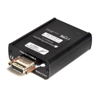
2. Connect the Pan-Tilt Unit to the Pan-Tilt Controller using the supplied cable. Note that the
smaller cable connector attaches to the pan-tilt unit, and the larger cable connector attaches
to the controller box. Securely screw the cable connectors to the pan-tilt unit and controller.
3. Connect the host terminal or computer to the Pan-Tilt Controller (PTU-C) using the RS-232
cable you supply (as described in Section 3.2). Configure the host RS-232 port as described
in Section 3.2. For initial set-up, it is suggested that you use a terminal or terminal emulator
on a host computer to become acquainted with the unit and its commands. For example, in
Windows you can use HyperTerminal, and in UNIX there is TIP (terminal interface
program).
4. You are now ready to power up the pan-tilt unit and test its operation. Plug the power plug
into the pan-tilt controller PTU-C (see Section 3.1 for a discussion of power source options).
Upon power up, introduction text should appear on your screen, and the pan-tilt unit should
go through a reset cycle. This reset is completed when an asterisk (‘*’) appears. If the unit
did not reset properly, recheck your power source and cabling. If the unit went through its
reset procedure, but no text or garbled text appears on your screen, then:
• Check that the host RS-232 host port settings are correct (see Section 3.2)
• Check that the RS-232 cable is correct for your host (see Section 3.2)
5. You are now connected to the pan-tilt controller. Enter the character ‘?’ for a complete
listing of commands. The next section describes some basic commands to help you get
going, and a full command description may be found in Section 4. We suggest that you
exercise the unit and become familiar with its operation and commands before mounting
your payload (e.g., camera) as described in Section 3.5.
3.4 Basic Pan-Tilt Unit Commands
Below are some pan-tilt commands that will familiarize you with the pan-tilt unit and its
operation:
pp2500 *
tp-900 *
ps2500 *
pp0 *
This sets the pan axis to position 2500, the tilt axis to position -900, the pan speed to 2500
positions a second, and sets the pan position back home.
When operating the pan-tilt unit, the available command menu is printed when you enter the
‘?’ character. A detailed description of pan-tilt commands and queries may be found in Section 4.
CAUTION! Failure to securely screw the supplied cable
connectors to the pan-tilt unit and controller can cause damage to
the controller when power is applied.