page 30
NETWORKING PTU-D46 User’s Manual (v2.14.0)
7 NETWORKING
The PTU controller lets you connect up to 127 PTUs to a single host computer port. Your
host computer can then address each PTU on the network as though the PTU were the only
controller attached to the host. In this way, it is simple to migrate existing code developed for a
single PTU to a network of PTUs controlled by a single host computer.
This section describes the basic installation and setup steps required to network your pan-tilt
units.
7.1 Basic Networking Setup Steps
The steps in networking your PTU controllers to your host computer are:
1. Sketch out the physical placement of your PTU controllers and host computer.
2. Assign a unique network ID number to each PTU controller.
3. Connect the PTU controllers and host computer to the PTU network.
4. Test the configuration by addressing each PTU controller by its unit ID and commanding
and querying its attached pan-tilt unit.
7.2 PTU Network Connections
Figure 6 illustrates how PTU controllers can be networked and connected to a host computer
via its RS-232 port. Each PTU controller has a built-in RS-232 to RS-485 converter, and the host
computer can be connected to the RS-485 controller network by simply connecting to the RS-232
connector on a PTU controller box. The PTU controllers are then connected together via an RS-
485 multi-drop network (full duplex).
The basic start configuration for networking PTU-controllers may be made using the PTU
Network Starter Kit (model PTU-D46-NET-SK). This starter kit includes two Y-connectors used
to connect to each of two PTU controllers, a data connection cable, and two network terminators.
Additional PTU controllers may be networked using the PTU Network Addition Unit Kit (model
PTU-D46-NET-AU), and this includes an additional Y-connector and data connector cable.
Figure 7 shows the wiring from the PTU RS-485 controller network receptacle (RJ-12,
6P6C). Several issues are important to note when you make your own data cables. First, use a
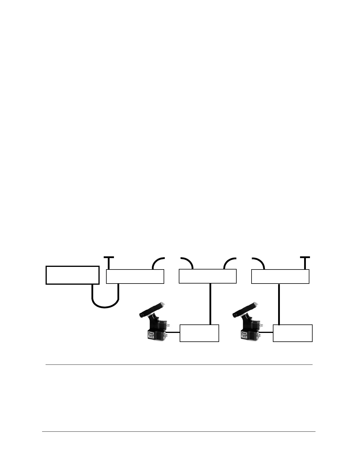
Figure 6: Making PTU Network Connections
HOST
COMPUTER
net/termin. network
PTU-NCONN
PTU
Controller
PTU
Controller
120Ω 1% terminator
network net/termin.
PTU-NCONN
120Ω 1% terminator
net/termin. network
PTU-NCONN
• • •
• • •
RS-485 Multi-Drop Network
(full duplex)