page 28
PTU OPTIONS PTU-D46 User’s Manual (v2.14.0)
maximum tilt up. For both axes, about 2-3VDC is a deadband in which no axis movement occurs;
this accomodates for slight inaccuracies in the joystick, its home position, and internal A/D
conversion.
If you wire your own analog joystick port input, use the 5VDC supplied by the controller. Do
not supply your own 5VDC. A voltage outside the range of 0-5VDC to the joystick will damage
the internal A/D converter and void the warranty. Ensure your voltage controls stay within the
required voltage range.
A standard IBM PC compatible joystick may be rewired to function with the EIO analog
joystick port. Analog PC joysticks are actually wired as variable resistors rather than
potentiometers. (Historically, this is because A/D converters were expensive when the PC
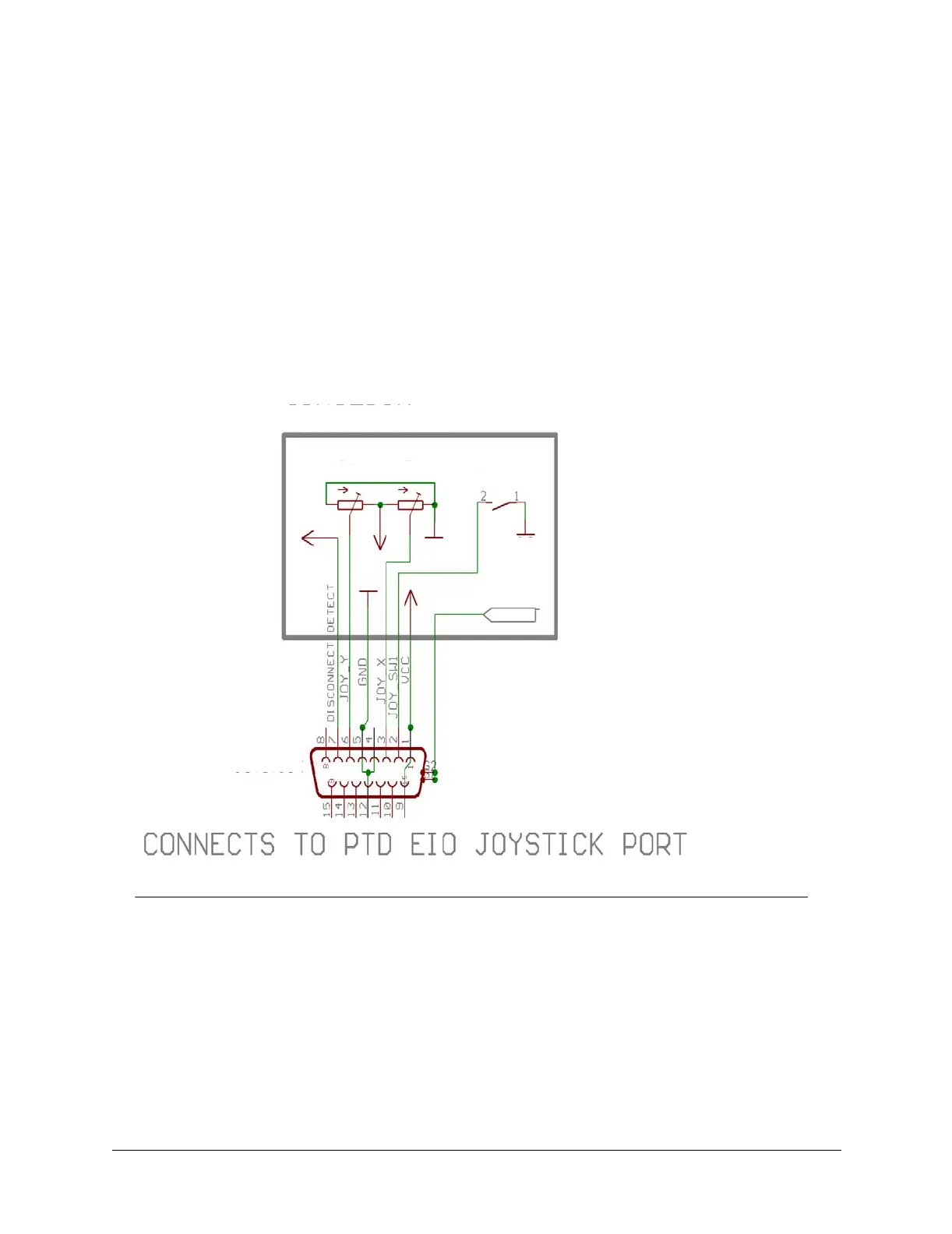
joystick was designed, so they kludged a shift register to do the job.) Figure 5 shows how to
rewire a standard analog PC joystick to operate with the EIO option analog joystick port.
Essentially, the rewire converts the variable resistor into a 100K potentiometer, and switch 2 is
grounded so that the PTU controller can determine that a joystick is attached.
6.1.4.1 Expansion Analog Joystick Commands
Description
Two PTU controller commands were added to support the EIO joystick port
to activate and deactivate it. When the joystick is centered in its X-Y range,
no commands are sent to move the pan-tilt. Host computer serial PTU
commands may be executed when the joystick is centered. When the joystick
is moving, they override the most recent serial PTU commands. The joystick
center range allows some position slop, called a deadband, to ensure that the
Figure 5. Wiring for the PTUC-EIO Analog Joystick Control Port
X: 0V is max left, 5V is max right, 2-3V deadband
Y: 0V is max down, 5V is max up, 2-3V deadband
SW: normally open, close to ground
button1
Y_POT
X_POT
100K
100K
JOYSTICK
GND
Vcc
Vcc
GND
Vcc
joystick
DB15M
shield
GND