7
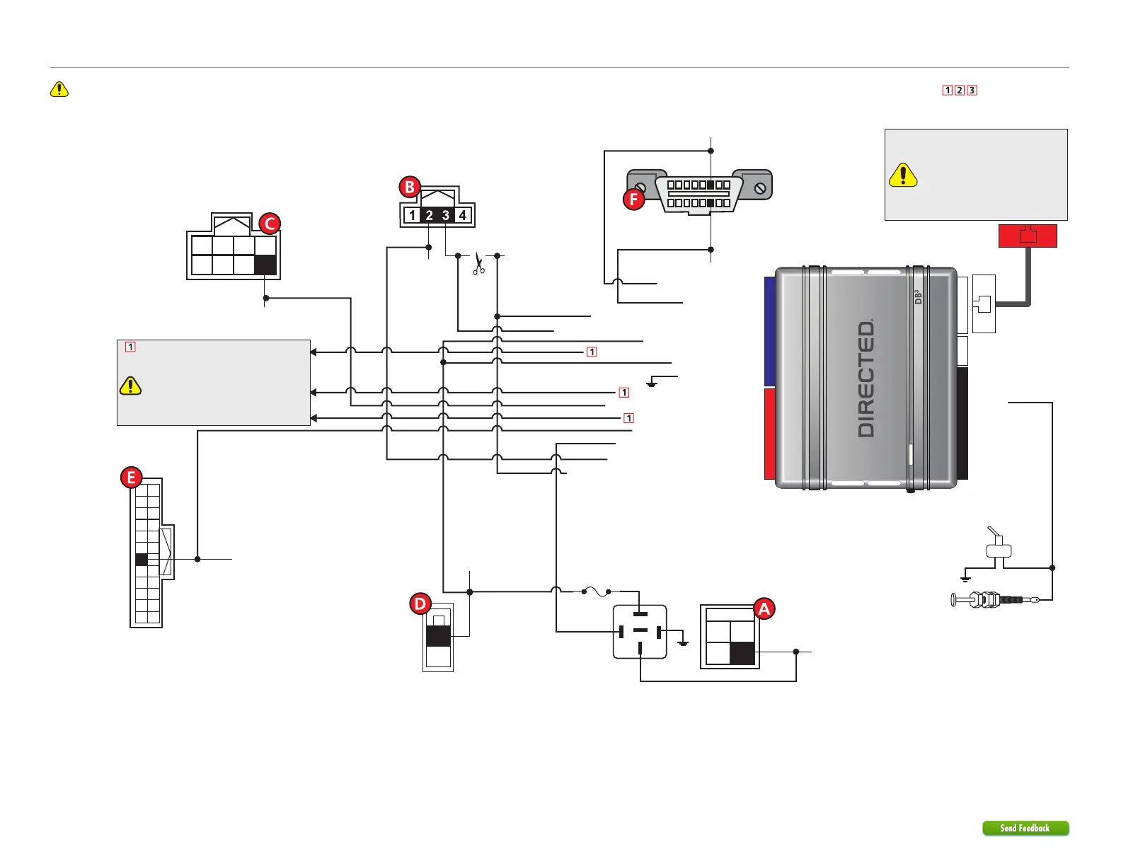
403.NISS4HT 2.39 2016 Nissan Versa (Smart Key)
©2022 VOXX•DEI LLC. All rights reserved.
Refer to "Pre-installation and application warnings" for important information, such as the description of each special note referenced in the diagram ( ).
Wiring diagram
Immo. Data Interrupt (veh. side): Yellow: 8
Immo. Data Interrupt (conn. side): Orange/Yellow: 9
(+) 12V Input: Red: 13
(-) Ground: Black: 14
HS CAN Low: Tan: 4
Immo. Clock Output: Yellow/Black: 10
(+) Brake Activation Output: Gray: 6
Immo. Data Output (veh. side): Orange/Black: 11
HS CAN High: Tan/Black: 3
6: White/Black:
(-) Hood
Remote Start Safety
Override Switch
Hood Pin
Note: hood pin only
required on vehicles not
equipped with a factory
hood pin.
You can connect to either a
XL202 RFTD OR a SmartStart
module.
Refer to the SmartStart/XL202
Installation Notes for more
information.
OBDII
Diagnostic Connector
(-) Push-to-Start Output: Green/Black: 2
(-) Unlock Output: Black/White: 1
(-) Lock Output: Green/White: 3
(-) RAP Off Output: Red/Black: 4
1 8
169
NATS Antenna Conn.
(behind Push-to-Start
button)
HS CAN Low:
Pink, pin 14
HS CAN High: Blue, pin 6
Data: Lt.Green, pin 3
Clock: Pink, pin 2
White 4-pin conn.
(Brake Switch)
3
1
4
2
30
86
85
87
87a
Fuse 10A
PTS - Brown 8-pin conn.
(at PTS switch)
(+)12V: Green, pin 1
Black 2-pin conn.
(at drivers kick)
1
2
(-) PTS: Blue, pin 8
8
1234
765
(-) Driver Door
Trigger: Lt.Blue, pin 18
12
24
11
23
10
22
9
21
8
20
7
19
6
18
5
17
4
16
3
15
2
14
1
13
Junction -
White 24-pin conn.
(at drivers kick)
(+) Brake: Lt. Green, pin 2
(+) 12V Input: Yellow/Red: 11
(+) Parking Lights Output: Brown/Red: 12
[2] (-) Lock, (-) Unlock wires and Parking Light
See ‘Vehicle Connections’.
Lock, Unlock and Parking wires must
be connected if the door lock and
OEM alarm are not controlled by data.
See features 5 & 7 in ‘Feature and Option
List’.
CUT
 Loading...