User manual in Original
Doc. ref: 500A_MC_am_en_210602
DISPERATOR AB Tel: 08-724 0160 E-mail: info@disperator.se
Mälarvägen 9, 141 71 Segeltorp Web page: www.disperator.se
37 / 44
36 / 44
9.3. Overhaul of Protection Cover with Switch, Assembly and Connections
The below designaons within brackets refers to the posion numbers on the exploded view drawing
with associated spare part list of the disposer in secon 9.2.
The following checks of the machine must be done in accordance with the table in secon 9.6,
“Overhaul and Maintenance Intervals” – i.e. make sure that:
• all screws and nuts (P18) between disposer and assembly are ghtened and in good condion,
• disposer connecon to the sewer pipe is sealed and xed,
• the ushing water connecon for disposer is sealed and xed,
• all cable glands are ght and xed,
• the disposer is securely xated either to the wall/bulkhead or the oor/oor plate.
9.4. Dismantling of Disposer
The below designaons within brackets refers to the posion numbers on the exploded view
drawing with associated spare part list of the disposer in secon 9.2.
1. Use the main electrical security breaker on the wall/bulkhead to disconnect electrical supply and
lock the breaker with a padlock.
2. Disconnect the ushing water supply to the disposer by closing a valve in the supply line.
3. Disconnect the disposer motor (P1) connecon cable from the start & stop control unit.
4. Disconnect the water trap from the disposer outlet on the end shield (P3).
5. Use a trolley which liing plate can be inserted under the disposer, or alternavely a steady jack
with liing plate. Detach the disposer from the assembly (6 screws and nuts, P18), and remove
possible disposer xaon from the wall/bulkhead or oor/oor plate. Move the disposer to a
suitable workbench for the connued dismantling.
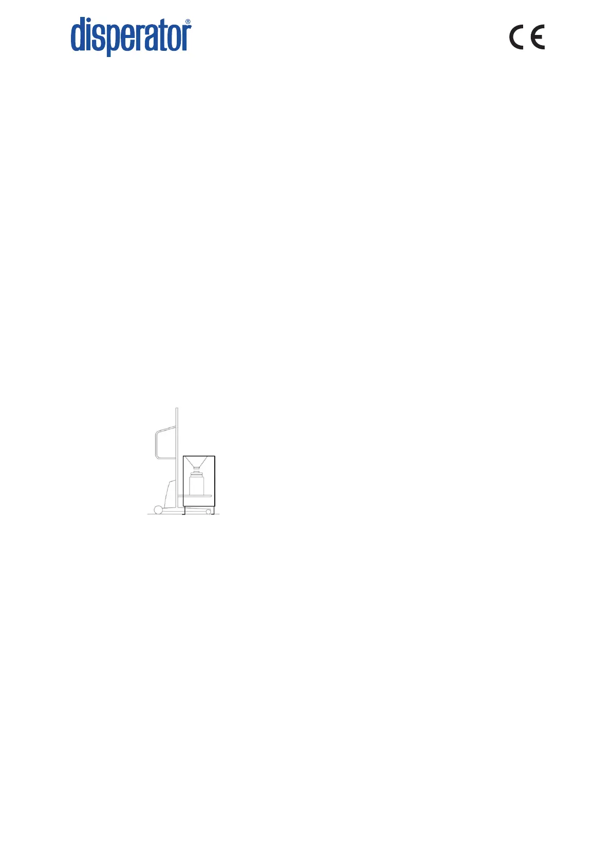
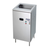
For disposers installed in closed cabinets (e.g. the models in 500-MB and 500-MC series) the
parts with posion number (P19) up to and including (P25) are not used. For these start the
dismantling of the disposer from item 8 below by loosening the four nuts with washers (P16).
6. Turn the grinder upside down and remove the housing (P20) by loosening the two screws (P23),
and loosen the cable gland (P22) and insert the cable into the housing.
7. Mark on the end shield (P3) the posion of the strap (P19) and then remove it by loosening two
nuts (P16). Turn the grinder over again. Loosen the remaining two nuts with washers (P16).
8. These four nuts (P16) must always be changed for new ones before reassembly, as they are
lock nuts. Note the locaon of the disposer outlet on the end shield (P3) relave to the hole
paern on the hood (P15) upper side, so that the outlet later may be reassembled in the same
direcon. For this purpose, is also an arrow engraved on the hood (P15) lower edge, which when
reassembling shall be above the outlet of the end shield (P3). Remove the hood (P15).
9. Remove the seal (P14) on the staonary shredder. This seal must always be replaced with a new
seal when reassembled.