User manual in Original
Doc. ref: 500A_MC_am_en_210602
DISPERATOR AB Tel: 08-724 0160 E-mail: info@disperator.se
Mälarvägen 9, 141 71 Segeltorp Web page: www.disperator.se
40 / 44
9.5. Assembly of Disposer
1. Clean all components carefully. Wipe the surface of the motor (P1) upper ange and its sha.
Make sure that there is no dust or grease residue.
2. Make sure that the motor sha key (P30) is in the correct posion. Apply a thin layer of
Disperator special grease (P26) on the motor sha.
3. Wipe the carrier (P2) clean on the inside and outside.
4. Mark onto the motor sha the depth of the hole in the carrier (P2). From the top of the motor
sha, this measure is 38 mm for models 510, 515, and 48 mm for model 520, and 58 mm for
models 530, 550 and 575. Carefully press the carrier (P2) onto the motor sha all the way down
to the mark. If hand power is not enough, use the axle screw (P12) as a mounng tool. If needed,
use the rotary shredder (P10) as a handle to prevent the carrier from rotang.
5. On the end shield (P3), clean the center hole for the axle seals (P5).
6. Place the washer (P4) in the end shield with the ange facing towards the motor (see the sketch
below under item 8, where the parts are seen with the end shield placed upside down as on the
photo to the le).
7. Grease the sealing face of this center hole in the end-shield (P3) with special grease (P26).
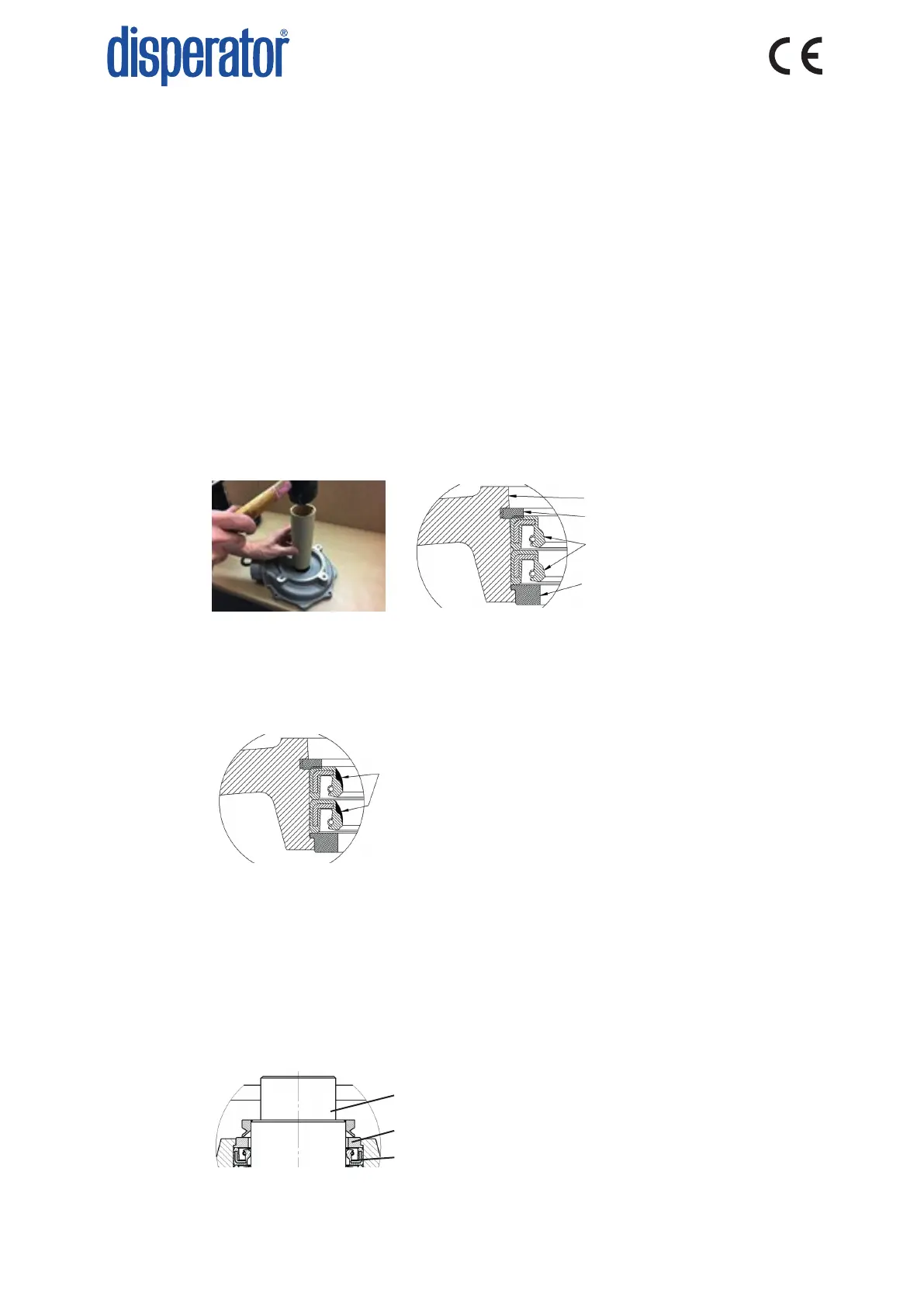
8. To avoid damaging the seals (P5, 2pcs), press each seal one at the me into posion in the end
shield using a tool (for example a sha end or other round bar, see below photo) that has the
same outer diameter as these seals. The seals shall be placed with the opening and stainless
spring upwards towards the washer (P4) according to the below sketch.
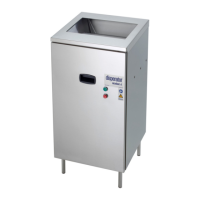
9. The seals are xated by ng the locking ring (P6) into the groove in the end shield (P3)
according to the above sketch under item 8. Tap on this ring to ensure that it is seated properly
in the groove in the end shield.
10. With a clean and so puy knife ll the grooves along the sealing lips in the axle seals (P5) with
special grease (P26). Be sure no dirt or parcles happen to fall into this greasing.
11. With a clean so cloth lubricate a thin layer of special grease (P26) on the carrier (P2) sealing
surface for the axle seals (P5).
12. With reference to secon 9.4, item 13 above, ret the end shield (P3) so that its outlet ends up
180° oset from the motor (P1) terminal box for cable connecon. Take great care so that the
lips on the axle seals (P5, 2pcs) not are damaged. For disposer models 510, 515 and 520 secure
the end shield with ghtening torque 47 Nm on the four screws (P7), and for models 530, 550
and 575 secure the end shield with ghtening torque 81 Nm on the four screws (P7).
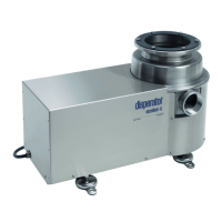
13. Grease the sealing lip of the V-ring seal (P8) and its seal washer (P4) using special grease (P26).
Fit the V-ring seal over the carrier (P2) with its seal lip against the seal washer (P4).
P3
P6
P5
P4
P26
P2
P8
P4