User manual in Original
Doc. ref: 500A_MC_am_en_210602
DISPERATOR AB Tel: 08-724 0160 E-mail: info@disperator.se
Mälarvägen 9, 141 71 Segeltorp Web page: www.disperator.se
41 / 44
40 / 44
14. Insert a small click of special grease (P26) into the keyway of the carrier (P2) and push on the key
(P9).
15. Wipe clean the axle hole in the rotary shredder (P10). Also make sure that the mang surfaces
on the end shield (P3) and the staonary shredder (P13) are clean.
16. Carefully t the rotary shredder (P10) on the carrier (P2).
17. Wipe the carrier (P2) clean from excess grease.
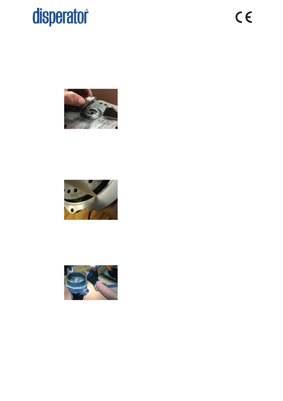
18. Apply a layer of rubber sealing compound (P27) over the joint between rotary shredder and
carrier (see photo below). Make sure that no sealing compound enters the screw hole of the
carrier.
19. Fit the axle washer (P11) on the rotary shredder. Apply rubber sealing compound around the
underside of the enre head of the axle screw (P12) and mount this screw. Make sure that
sealing compound is squeezed out around the enre circumference of the axle washer, and also
around the enre head of the axle screw. For disposer models 510 and 515 the axle screw is
ghtened with torque 9,3 Nm, and for model 520 the axle screw is ghtened with torque 22 Nm,
and for models 530, 550 and 575 the axle screw is ghtened with torque 44 Nm.
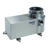
20. Apply a thin uninterrupted string of rubber sealing compound (P27) in the seat of the end shield
(P3) in which the staonary shredder (P13) should be pressed down. See below photo.
21. Carefully posion the staonary shredder (P13) with its upper large tooth closest to the outlet of
the end shield (P3).
22. Tap around the top of the staonary shredder (P13) with a plasc hammer to x it in the end
shield (P3), and make sure that the staonary shredder is all the way down in the seat of the end
shield.
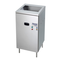
23. Secure the staonary shredder (P13) to the end shield (P3) by hammering 6 punch marks on the
end shield with even distances around the joint between these two arcles. See below photo.
24. Fit a new rubber seal (P14) on the top of the staonary shredder (P13). Make sure that it is
centered.
25. Wipe clean the surface of the hood (P15) that faces the rubber seal (P14).
26. Carefully t the hood (P15). For the upper hole paern of the hood to end up in the same way as
before dismantling, the outside arrow mark on the hood lower edge shall be posioned centrally
above the waste outlet on the end shield (P3). This to make sure that the disposer outlet will
have the same direcon towards the sewer connecon as before. Also feel with your ngers that
the seal (P14) sll is centered.