4 / 15
Daisy-chaining controllers is not permitted when a controller’s expected power consumption including external loads is over 15VA. In this case the con-
troller must be connected to the 24VAC transformer in a star topology. The transformer must be installed in close proximity to the controller according to
the cable gauge and total load.
AWG Power Run Total Cable Length Maximum Number of Devices
@ 7 VA per device
1
Maximum Number of Devices
@ 10 VA per device
2
Maximum Number of Devices@
15 VA per device
3
14
4
75M (250 feet) 4 2 1
14
4
60M (200 feet) 5 3 2
14
4
45M (150 feet) 5 4 3
14
4
30M (100 feet) 5 5 4
16 60M (200 feet) 3 2 1
16 45M (150 feet) 5 3 2
16 30M (100 feet) 5 4 3
18 45M (150 feet) 3 2 1
18 30M (100 feet) 5 3 2
Table1: Maximum Number of VAV Devices on a Power Run (Daisy-Chained)
1. Typical VAV with 1 Allure Series Communicating Sensor(without CO
2
sensor) and actuator activated. No external loads.
2. Typical VAV with 1 Allure Series Communicating Sensor (without CO
2
sensor), 2 triac loads (1.6 VA each), 1 analog output (20 mA), and actuator activated.
3. Typical VAV with 1 Allure Series Communicating Sensor (without CO
2
sensor), 4 triac loads (1.6 VA each), 2 analog outputs (20 mA each), and actuator activated.
OR
Typical VAV with 1 Allure Series Communicating Sensor with CO
2
sensor, 2 triac loads (1.6 VA each), 1 analog output (20 mA), and actuator activated.
4. Device terminals are not capable of accepting two 14 AWG wires (when daisy-chaining devices). Use a wire nut with a pig tail to make such a connection.
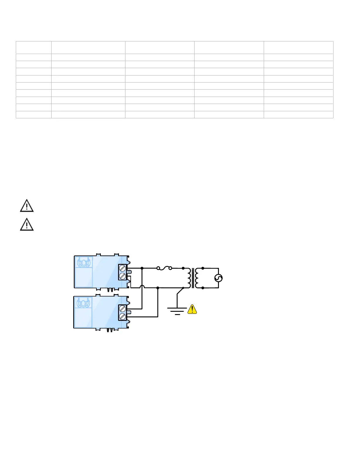
Use an external fuse on the 24VAC side (secondary side) of the transformer, as shown below, to protect all controllers against power line spikes.
Maintain consistent polarity when connecting controllers and devices to the transformer. One terminal on the secondary side of the transformer must be
connected to the building’s ground. All 24V COM terminals of all controllers and peripherals throughout the BACnet MS/TP network must be connected
to the grounded transformer terminal as shown below. This ensures that the 24V COM terminals of all devices connected to any BACnet MS/TP bus in
the building are at the same potential.
A mechanical ground is unacceptable: Do not use a pipe, conduit, or duct work for a ground. The power supply must
have a dedicated ground wire that comes from the main electrical supply panel.
Failure to maintain consistent polarity throughout the entire network will result in a short circuit and/or damage to the
controller!
The COM terminals of the controller are internally wired to the 24V COM terminal of the power supply. Connecting a
peripheral or another controller to the same transformer without maintaining polarity between these devices will
cause a short circuit.
Controller 2
Transformer
Controller 1
AC
24V AC
24V COM
Fuse: 4 A Max.
Fast Acting
24 VAC
Electrical System Ground
- At Transformer Only
24V AC
24V COM
Figure3: Power Wiring