8 / 15
Communications Wiring
The Network Guide provides extensive information and requirements to implement a BACnet MS/TP network. It contains information about network and
sub network length, cable type, device addressing, etc. It can be downloaded from the Distech Controls’ Documentation and Resources portal.
For optimal performance, use Distech Controls 24AWG (0.65 mm) stranded, twisted pair shielded cable or refer to the Network Guide for cable specifi-
cation. The BACnet MS/TP communication wire is polarity sensitive and the only acceptable topology is to daisy-chain the cable from one controller to
the next.
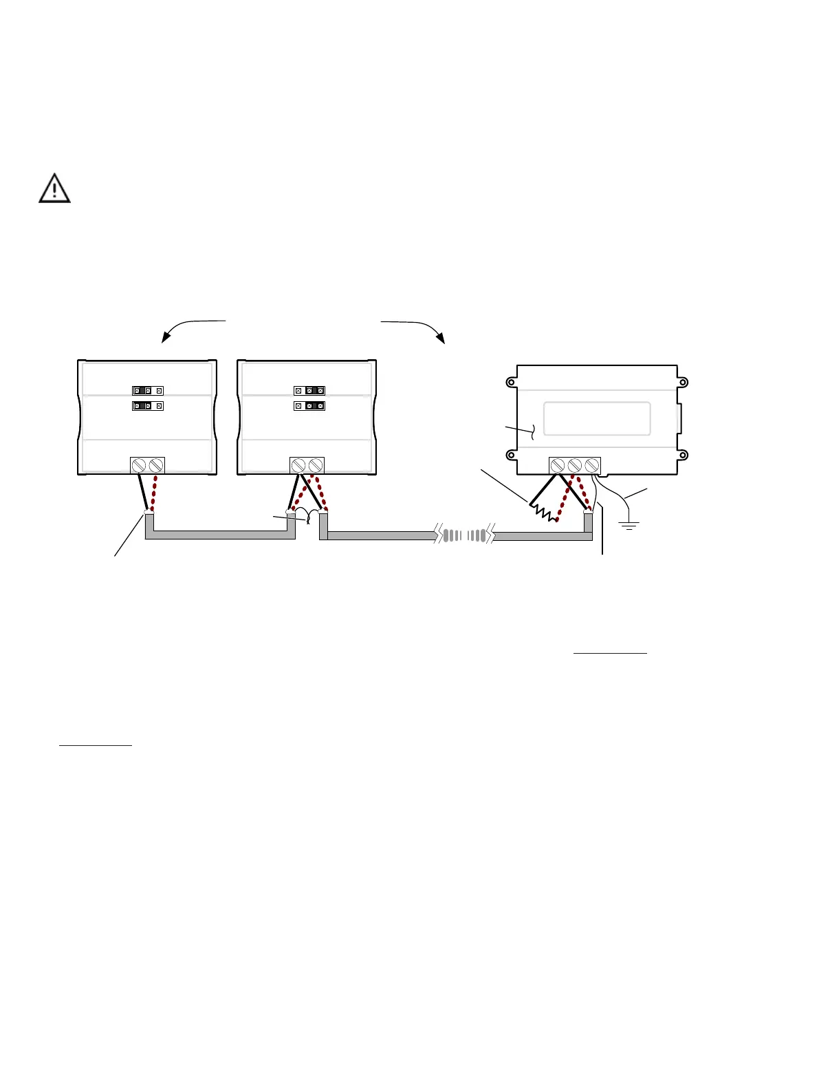
As shown in BACnet MS/TP Communications Wiring:
£ The first and last daisy-chained BACnet MS/TP device must have its EOL resistors enabled / installed. All other
devices must have their EOL resistor disabled (default factory setting).
£ When the BACnet MS/TP data bus is connected to a following device, twist data bus shields together.
£ Isolate all shields with electrical tape so there is no exposed metal that can touch ground or other conductors.
£ The shield of the data bus must be connected to the electrical system ground at only one point – usually at one
end of the bus as shown below.
£ Connect no more than 50 devices to a BACnet MS/TP data bus.
Data Bus Shield: Connect
to the ‘S’ terminal
Typical BACnet Device
First and last daisy-chained device:
-
- EOL Jumpers are ON
All other Devices::
- EOL Jumpers are OFF
EOL ON: For the EC-BOS
AX
as the first or last daisy
chained device:
- OPTIONALLY set the EOL
jumper internally
- AND add a 120 Ohm EOL
resistor as shown here
NET+
NET-
Typical BACnet Device
NET+
NET-
Typical EC-BOS
AX
Device
EOL ON EOL OFF
+-
S
Data Bus: Shielded Twisted Pair Cable
Data Bus Shield:: Isolate with
electrical tape
Data Bus Shields: Twist
together and isolate
with electrical tape
Up to 50 Devices Total
1
2
0
Ω
The shield of the
data bus must be
connected to the
electrical system
ground at only one
point – usually at
one end of the bus
as shown.
Figure5: BACnet MS/TP Communications Wiring
If inserting multiple wires in the terminals, ensure to properly twist wires together prior to inserting them into the terminal connectors.
For more information and detailed explanations on network topology and wire length restrictions, refer to the Network Guide, which can be downloaded
from the Distech Controls’ Documentation and Resources Portal.
Device Addressing
The Network Guide provides extensive information and requirements to implement a BACnet MS/TP network. It contains information about network plan-
ning and MAC Address numbering schemes. It can be downloaded from the Distech Controls’ Documentation and Resources Portal.
The MAC Address must be set according to your network planning document by setting the DIP switch located under the cover or when this DIP switch
is set to 0 (all off), the MAC address can be set by connecting an Allure EC-Smart-Vue Series Communicating Sensor to the controller as shown in Step
5 of
Setting the Communicating Sensor Subnet ID
in the following section. An example of how to set the device’s MAC Address DIP switch is shown be-
low.