3 / 15
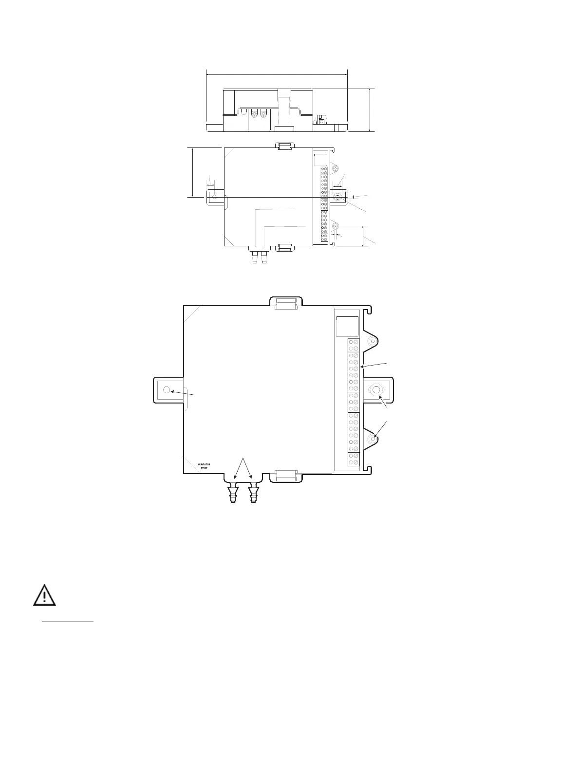
Controller Dimesions and Components
Low pressure
High pressure
Bracket
mouting kit
190 [7.48 ]
54 [2.13 ]
61.5 [2.42]
10
[0.40]
3 mm
0.12 in
26.5 [1.04]
11
[0.43]
5 [0.2]
Units Legend: mm [in]
Figure1: VAV-N & 103 dimensions
Connectors
Integrated
Mounting
Brackets
Pressure Sensor Inputs (when equipped)
PRESSURE
LOW
HIGH
Integrated
Mounting
Bracket
Figure2: VAV-N & 103 components
Power Wiring
Voltage:
24VAC/DC; ± 15%, Class 2
This is a Class 2 Product. Use a Class 2 transformer only (rated at 100VA or less at 24VAC) to power the
controller(s).
The Network Guide provides extensive information and requirements for powering a controller that uses a BACnet network for communications. It can be
downloaded from Distech Controls’ Documentation and Resources Portal.
It is recommended to wire only one controller per 24VAC transformer.
When calculating a controller’s power consumption to size the 24VAC transformer, you must also add the external loads the controller is going to supply,
including the power consumption of any connected subnet module (for example, Allure™ Series Communicating Sensors). See the room device calcula-
tor spreadsheet to determine the power requirements for the VAV model:
VAV-Smart Room Control Device Calculator.xlsm
available on the Distech
Controls’ Documentation and Resources Portal.
If only one 24VAC transformer is available, determine the maximum number of daisy-chained VAVs that can be supplied on a single power cable sup-
plied by a 100 VA transformer, according to the controller’s expected power consumption including external loads, the cable’s wire gauge, and the total
cable length from the following table. Any installation condition that is outside of the parameters Table 1 should be avoided.