5 / 15
DIP Switch and Jumper Configuration and Identification
Controllers have the following onboard configurable jumpers and DIP switches.
BACnet MS/TP Network
EOL Termination
* Factory-default positions
Subnet
Port
EOL Off
(Disabled)*
EOL On
(Enabled)
Wireless
Port
Jumpers for
DO1 & DO2
Jumpers for
DO3 & DO4
Typical locations: Quantity may vary according to controller model
Digital Outputs (DO)
Power Source
Triac Internal
Power*
Triac External
Powered
ON
S1
1 2
3 4 5 6 7 8
MAC Address DIP Switch
(S1)
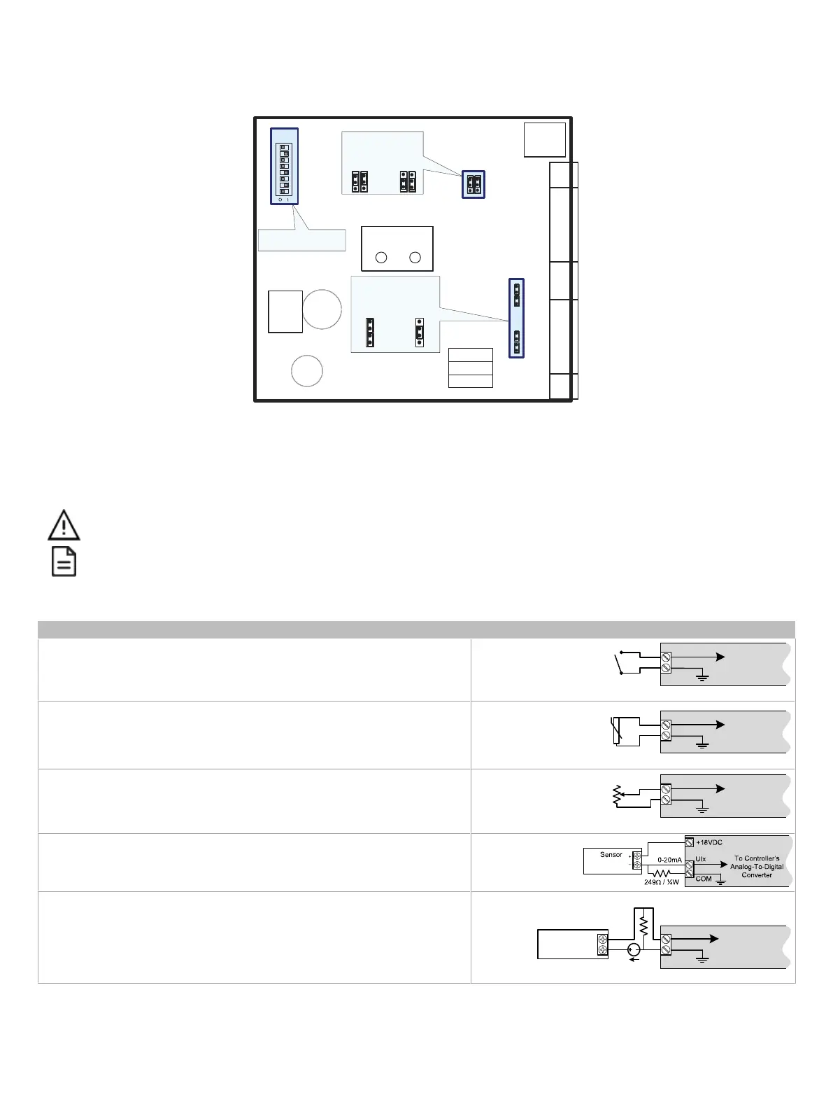
Figure4: ECB-VAV-N and ECB-103 Jumpers and DIP Switches
Input Wiring
Before connecting a sensor to the controller, refer to the installation guide of the equipment manufacturer.
£ For a wire length less than 75’ (23m), either a shielded or unshielded 18AWG wire may be used.
£ For a wire up to 200’ (61m) long, a shielded 18AWG wire is recommended.
£ The shield of the wire should be grounded on the controller side only and shield length should be kept as short as possible.
Table 2 shows the available universal input (UIx) wiring methods
Sensor Input Type Input Connection Diagram
£ Dry Contact input.
UIx
COM
To Digital
Input
Digital Dry Contact
NO-NC
£ RTD input (for example, 1000Ω).
£ Thermistor Input (for example, 10kΩ type II and III).
UIx
COM
To Analog-
To-Digital
Converter
RTD/
Thermistor
£ Resistive input, maximum 350kΩ (for example, use with 10kΩ and 100kΩ poten-
tiometers).
UIx
COM
To Analog-
To-Digital
Converter
Potentiometer
10kΩ
£ 0 to 20mA input used with a 2-wire, 0 to 20mA sensor powered by the controller’s
internal 15VDC power supply.
£ 0 to 20mA input used with a 2-wire, 0 to 20mA sensor powered by an external 24
AC/DC power supply.
-
+
0-20mA
Sensor
UIx
COM
To Analog-
To-Digital
Converter
24VDC
249Ω ¼W