7 / 15
Output Wiring
Before connecting an output device (actuator, relay, etc.) to the controller, refer to the datasheet and installation
guide of the equipment manufacturer.
£ For a wire length less than 75’ (23m) long, either a shielded or unshielded 18AWG wire may be used.
£ For a wire length up to 200’ (61m) long, a shielded 18AWG wire is recommended.
£ The shield of the wire should be grounded on the controller side and the shield length should be kept as short
as possible.
£ For relay outputs (DOx); select appropriately-sized wiring suitable to the current load.
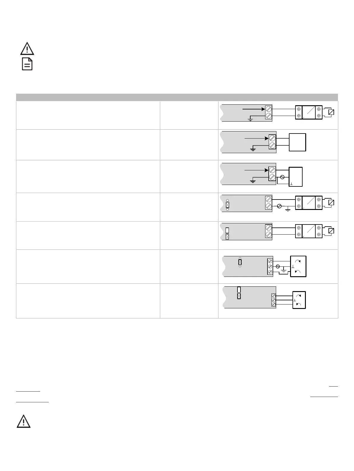
Control Output Type Output Designation Output Connection Diagram
£ Discrete 0 or 12VDC digital, Pulse, or PWM output controlling
a 12VDC relay
UOx
From
Digital
Output
12VDC Relay
A1
A2
UOx
COM
£ Linear 0 to 10VDC digital to analog output.
UOx
0-10V
Common
From Digital-
To-Analog
Output
UOx
COM
£ 0 to 10VDC voltage output controlling an analog actuator that
is powered by an external 24VAC power source.
UOx
0-10V
~ or +
From Digital-
To-Analog
Output
UOx
COM
Actuator
or -
24VAC
£ 24VAC externally-powered triac output controlling a relay
1
.
£ Set the jumper accordingly.
DOx
JUMPER
SETTINGS
24VAC Relay
A1
A2
DOx
Cx-x
AC
£ 24VAC internally-powered triac output controlling a relay
1
.
£ Set the jumper accordingly.
DOx
JUMPER
SETTINGS
24VAC Relay
A1
A2
DOx
Cx-x
£ 24VAC externally-powered triac output controlling a floating
actuator
1
.
£ Set the jumper accordingly.
DOx
DOx
Cx-x
Actuator
~
DOx
~
JUMPER
SETTINGS
24VAC
£ 24VAC internally-powered triac output controlling a floating ac-
tuator
1
.
£ Set the jumper accordingly.
DOx
DOx
Cx-x
Actuator
~
DOx
~
JUMPER
SETTINGS
1. Maximum output current for all digital triac outputs is 0.5A continuous or 1A @ 15% duty cycle for a 10-minute period.
Subnet Wiring
The subnet is used to connect a range of Allure Series Communicating Sensors:
£ The Allure EC-Smart-Vue Series sensor is a communicating room temperature sensor with backlit display graphical menus and VAV balancing ca-
pabilities.
£ The Allure EC-Smart-Comfort and Allure EC-Smart-Air Communicating Sensors are a range of communicating room temperature sensors.
Connect the Allure Series to the controller’s
Subnet Port
with a standard Category 5e Ethernet patch cable fitted with RJ-45 connectors. Refer to the Net-
work Guide for extensive information and requirements for the connection of the Allure Series. It contains information about network topology and length,
cable type, setting the Subnet ID, etc. It can be downloaded from the Distech Controls’ Documentation and Resources Portal. See also the Hardware In-
stallation Guide supplied with the Allure Series.
If you make your own patch cable, see the Allure Series Hardware Installation Guide.
Protect the controller’s connector from being pulled on when a cable to the Allure Series is connected. Create a
strain-relief by looping the cable and attaching it to a solid object with a nylon tie so that a tug on the cable will not
pull out the connector on the controller.