13 / 22
Input and Output Overview
Each ECY IO module has a number of physical connections for inputs and/or outputs. These inputs and outputs are labelled on the ECY IO modules ac-
cording to the tables below. Input and output options must be configured properly in EC-gfxProgram to ensure correct input readings and output values.
The controller's license may have separate limits that reduce the availability of certain options.
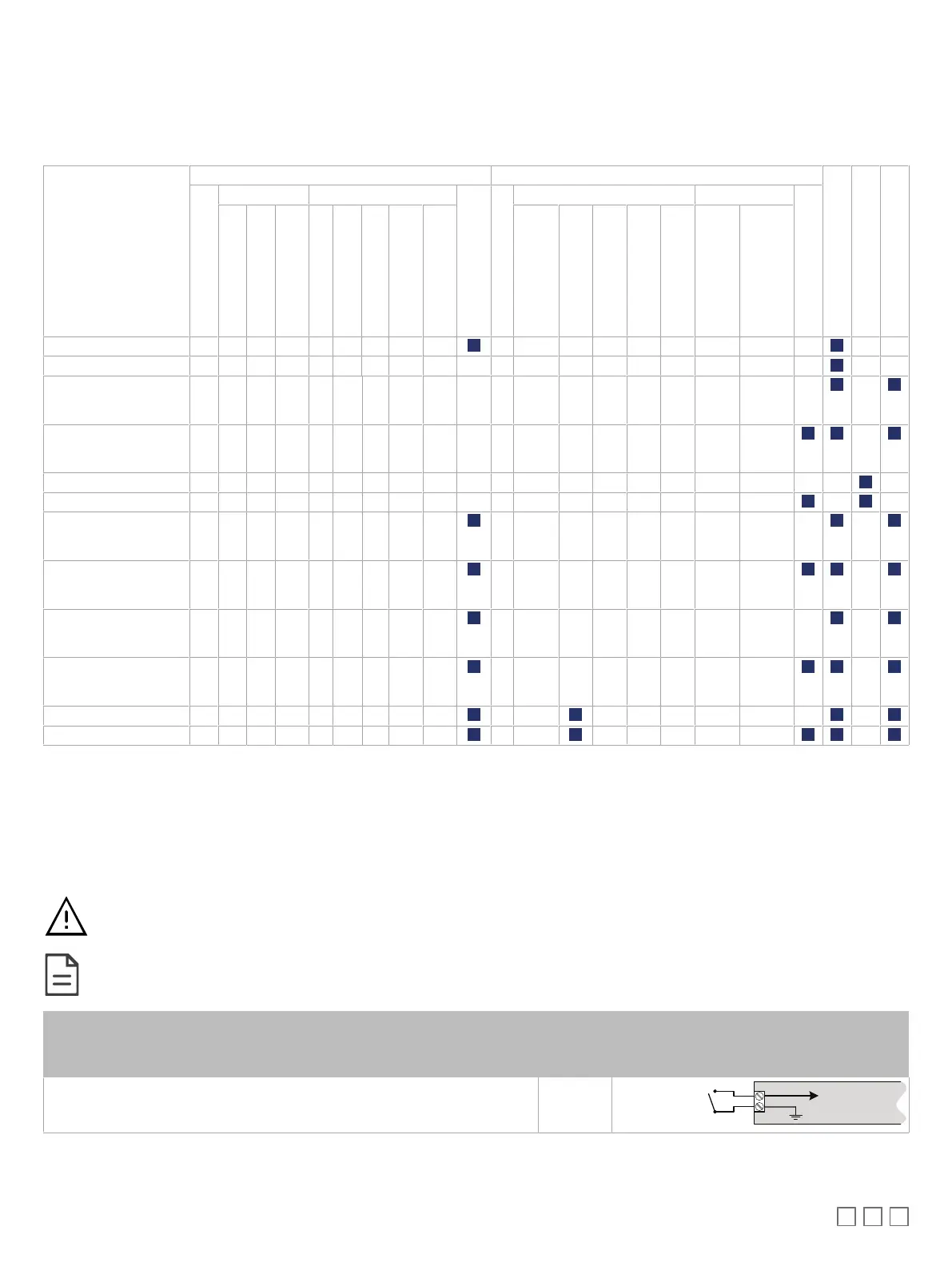
ECY IO Modules
Inputs Outputs
Narrow width
Wide width
DIP Switch to Configure I/Os
Quantity
Digital Analog
18VDC Power Supply
Quantity
Digital Analog
HOA
Contact
Counter
120Hz Pulse Counting
0 to 10VDC
0 to 5VDC
0 to 20mA
1
Resistance
Thermistor
0-277VAC / 0-30 VDC
Form-C, 10A
24VAC Triac
0 or 12VDC
PWM
Floating
0 to 10VDC
2
0 to 20mA
2
ECY-8UI 8 UIx UIx UIx UIx UIx UIx UIx
ECY-16DI 16 DIx DIx DIx
ECY-6UO 6 UOx UOx UOx UOx UO1
UO2
UO3
ECY-6UO-HOA 6 UOx UOx UOx UOx UO1
UO2
UO3
ECY-8DOR 8 DOx
ECY-8DOR-HOA 8 DOx
ECY-4UI4UO 4 UIx UIx UIx UIx UIx UIx UIx 4 UOx UOx UOx UOx UO1
UO2
UO3
ECY-4UI4UO-HOA 4 UIx UIx UIx UIx UIx UIx UIx 4 UOx UOx UOx UOx UO1
UO2
UO3
ECY-8UI6UO 8 UIx UIx UIx UIx UIx UIx UIx 6 UOx UOx UOx UOx UO1
UO2
UO3
ECY-8UI6UO-HOA 8 UIx UIx UIx UIx UIx UIx UIx 6 UOx UOx UOx UOx UO1
UO2
UO3
ECY-8UI6DOT 8 UIx UIx UIx UIx UIx UIx UIx 6 DOx DOx
ECY-8UI6DOT-HOA 8 UIx UIx UIx UIx UIx UIx UIx 6 DOx DOx
1. An on-board 18VDC power supply can provide the necessary power for 20mA current loop sensor operation. The 0 to 20mA current loop input option is individually selected through an on-board DIP
switch setting.
2. 0 to 10VDC is available on UO1 to UO6. 0 to 20 mA is available on UO1, UO2, and UO3; this option is individually selected through an on-board DIP switch setting.
Input Wiring
Input options must be properly configured in EC-
gfx
Program to ensure correct input readings. The table below shows the ECY IO modules’ input desig-
nation for each IO model. For terminal block connector wiring best practices, see General Wiring Recommendations [pg.2]. Inputs can be connected as
follows.
Before connecting a sensor to the controller, refer to the installation guide of the equipment manufacturer.
£ For a wire length less than 75’ (23m), either a shielded or unshielded 18AWG wire may be used.
£ For a wire up to 200’ (61m) long, a shielded 18AWG wire is recommended.
£ The shield of the wire should be grounded on the controller side only and the shield length should be kept
as short as possible.
Sensor Input Type ECY IO
modules’
Input Des-
ignation
Input Connection Diagram
£ Dry Contact input.
£ Pulsed input.
£ UIx
£ DIx
UIx, DIx or SIx
COM
To Digital Input
Digital Dry Contact
NO-NC