2 / 22
Device Markings (Symbols)
Certain markings (symbols) can be found on the controller and are defined as follows:
Symbol Description
CE marking: the device conforms to the requirements of applicable EC directives.
Double Insulation
marking: These controllers are built using double insulation.
Products must be disposed of at the end of their useful life according to local regulations.
Read the Hardware Installation Guide for more information.
For indoor use only.
UL marking: conforms to the requirements of the UL certification.
FCC marking: This device complies with FCC rules part 15, subpart B, class B.
Warning Symbol: Significant information required. Refer to the Hardware Installation Guide.
HIGH VOLTAGE Symbol: Direct contact will cause electrical shock or burn.
Alternating Current
Direct Current
Line
Neutral
General Wiring Recommendations
Risk of Electric Shock: Turn off power before any kind of servicing to avoid electric shock. However, it is not
necessary to remove power when hot-swapping SELV ECY IO module front assemblies (see Hot-swappable
ECY IO Modules).
Mise En Garde: Risque de décharge électrique: Débrancher l’alimentation avant de réaliser tout raccordement électrique afin d’éviter tout risque de décharge électrique. Cependant, il n’est pas nécessaire de débrancher l’alimentation pour échanger les façades des modules ECY IO TBTS à chaud (voir Hot-swappable ECY IO Modules).
£ All wiring must comply with electrical wiring diagrams as well as national and local electrical codes.
£ To connect the wiring to a device, use the terminal connectors. Use a small flat screwdriver to tighten the terminal connector screws once the wires
have been inserted (strip length: 0.25’’ (6mm), tightening torque 0.5 Nm).
£ Comply with all network and power supply guidelines outlined in the Network Guide.
£ It is strongly recommended to use unshielded CAT5e cables for ethernet communications.
£ Keep wiring separate according to their function and purpose to avoid any ambient noise transmission to other wires. Use strapping to keep these
wires separated. For example, keep power, hazardous voltage, SELV, PELV, network, and input wiring separate from each other.
£ For the ECY-PS24 Power Supply: When connecting one wire to a controller’s terminal block clamping cage (pole), the wire must be between 18 and
14 gauge (0.82 and 2.1mm
2
cross-sectional area). When connecting two wires to a controller’s terminal block clamping cage, both wires must be the
same thickness, must be between 18 and 16 gauge (0.82 and 1.3mm
2
cross-sectional area), and must be the same type (solid or stranded). Twist
the wires together and insert then into the controller’s terminal block clamping cage. For any other wiring combination (mixed wire thickness, mixed
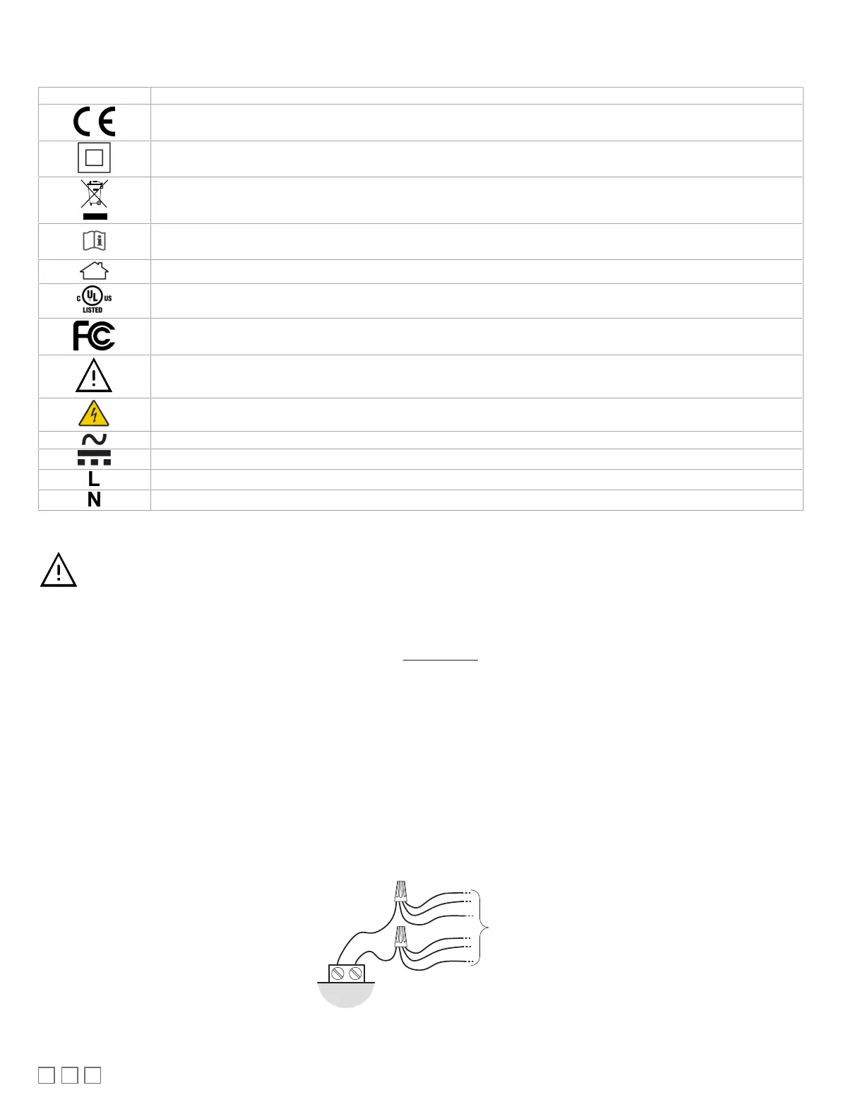
solid and stranded conductors, more than three wires, wire thickness is out of range), twist the wires together and use a wire nut and a pig tail to
connect to the controller’s terminal block connector as show below.
£ For ECY IO Modules: When connecting one wire to a controller’s terminal block clamping cage (pole), the wire must be between 22 and 16 gauge
(0.33 and 1.3mm
2
cross-sectional area). When connecting two wires to a controller’s terminal block clamping cage, both wires must be the same
thickness, both wires must be between 22 and 18 gauge (0.33 and 0.82mm
2
cross-sectional area), and both wires must be the same type (solid or
stranded). Twist the wires together and insert then into the controller’s terminal block clamping cage. For any other wiring combination (mixed wire
thickness, mixed solid and stranded conductors, more than three wires, wire thickness is out of range), twist the wires together and use a wire nut
and a pig tail to connect to the controller’s terminal block connector as show below.
Controller
Wire Nuts
Terminal Block
Connector
Wire Connections
Pigtails
Figure2: Using a Wire Nut and Pigtail to Wire the Controller
£ Do not connect the universal inputs, analog/digital outputs or common terminals to earth or chassis ground (unless stated otherwise).
£ Keep input and output wiring in conduits, trays or close to the building frame if possible.