14 / 22
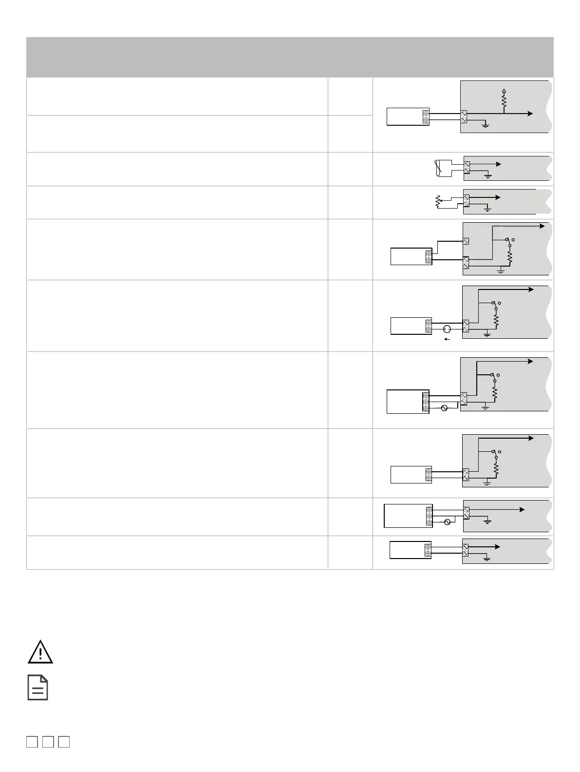
Sensor Input Type ECY IO
modules’
Input Des-
ignation
Input Connection Diagram
£ Pulse input used with a 2-wire sensor powered by its own power source – this in-
put supports a maximum input frequency of 1Hz (500ms minimum ON/OFF).
Connect the pulse input according to the figure for a pulse meter that can pull-
down a +5VDC supply with a 10KΩ pull-up resistor (Internal supply type).
£ UIx
Pulse Meter
Output
C
ontroller
P
ulse
Inpu
t
E
quivalent
Circuit
UIx or DIx
COM
To Pulse Count
Accumulator
+
-
10 kവ
+5 VDC
£ Pulse input used with a 2-wire sensor powered by its own power source – this in-
put supports a maximum input frequency of 120Hz (4.137ms minimum ON/OFF).
Connect the pulse input according to the figure for a pulse meter that can pull-
down a +5VDC supply with a 10KΩ pull-up resistor (Internal supply type).
£ DIx
£ RTD input (for example, 1000Ω).
£ Thermistor Input (for example, 10kΩ type II and III).
£ UIx
UIx or SIx
COM
To Analog-To-
Digital Converter
RTD/
Thermistor
£ Resistive input, maximum 350kΩ (for example, use with 10kΩ and 100kΩ poten-
tiometers).
£ UIx
UIx or SIx
COM
To Analog-To-
Digital Converter
3RWHQWLRPHWHU
Nവ
£ 0 to 20mA input used with a 2-wire, 0 to 20mA sensor powered by the controller’s
internal 18VDC power supply.
£ See DIP Switch and Jumper Identification and Configuration on page 5 for more
information about how to set the DIP Switch.
£ UIx
+
-
Sensor
0-20mA
Controller
0-20mA Input
Equivalent
Circuit
UIx
COM
To Analog-
To-Digital
Converter
249Ω
+18VDC
Current Input
Option Enabled
£ 0 to 20mA input used with a 2-wire, 0 to 20mA sensor powered by an external 24
AC/DC power supply.
£ See DIP Switch and Jumper Identification and Configuration on page 5 for more
information about how to set the DIP Switch.
£ UIx
-
+
Sensor
0-20mA
Controller
0-20mA Input
Equivalent
Circuit
UIx
COM
To Analog-To-
Digital Converter
249Ω
24VDC
Current Input
Option Enabled
£ 0 to 20mA input used with a 3-wire, 0 to 20mA sensor powered by an external 24
AC/DC power supply.
£ See DIP Switch and Jumper Identification and Configuration on page 5 for more
information about how to set the DIP Switch.
£ UIx
AC
+
Common
Sensor
0-20mA
Controller
0-20mA Input
Equivalent
Circuit
UIx
COM
To Analog-To-
Digital Converter
249Ω
24VAC
Current Input
Option Enabled
£ 0 to 20mA input used with a sensor powered by its own power source.
£ See DIP Switch and Jumper Identification and Configuration on page 5 for more
information about how to set the DIP Switch.
£ UIx
+
-
Sensor
0-20mA
Controller
0-20mA Input
Equivalent
Circuit
UIx
COM
To Analog-To-
Digital Converter
249Ω
Current Input
Option Enabled
£ Voltage input used with a 3-wire 0 to 10VDC or 0 to 5VDC sensor powered by an
external 24 AC/DC power supply.
£ UIx
AC
+
Common
0-10V
Sensor
UIx
COM
To Analog-To-
Digital Converter
24VAC
£ Voltage input used with a 0 to 10VDC or 0 to 5VDC sensor powered by its own
power source.
£ UIx
+
-
0-10V
Sensor
UIx
COM
To Analog-
To-Digital
Converter
Table1:
ECY IO Module Input Wiring
Output Wiring
Output options must be properly configured in EC-
gfx
Program to ensure correct output values. The table below shows the ECY IO modules’ output des-
ignation for each IO model. For terminal block connector wiring best practices, see General Wiring Recommendations [pg.2]. Outputs can be connected
as follows.
Before connecting an output device (actuator, relay, etc.) to the controller, refer to the datasheet and installation
guide of the equipment manufacturer.
£ For a wire length less than 75’ (23m) long, either a shielded or unshielded 18AWG wire may be used.
£ For a wire length up to 200’ (61m) long, a shielded 18AWG wire is recommended.
£ The shield of the wire should be grounded on the controller side and the shield length should be kept as
short as possible.
£ For relay outputs (DOx); select appropriately-sized wiring suitable to the current load.