CROSS5E CROSS5EH CROSS7E CROSS7EH CROSS8E
Power supply 230 V~ / 50 Hz 230 V~ / 50-60 Hz 230 V~ / 50 Hz 230 V~ / 50-60 Hz 230 V~ / 50 Hz
Absorption 1,5 A 1,2 A 2 A 1,5 A 3 A
Thrust 500 N 400 N 700 N 600 N 800 N
Condenser 12,5 µF - 16 µF - 22 µF
Max run 20 m 20 m 20 m 20 m 20 m
Door speed 0,18 m/s 0,09 - 0,21 m/s 0,18 m/s 0,12 ÷ 0,20 m/s 0,18 m/s
Max door weight 400 kg 450 kg 600 kg 600 kg 800 kg
Service class 3 - FREQUENT 4 - INTENSIVE 4 - INTENSIVE 4 - INTENSIVE 4 - INTENSIVE
Min number of
consecutive cycles
20 50 30 50 30
Intermittence
S2 = 15 min
S3 = 25%
S2 = 30 min
S3 = 50%
S2 = 20 min
S3 = 50%
S2 = 30 min
S3 = 50%
S2 = 20 min
S3 = 50%
Temperature -20 °C/+55 °C -20 °C/+55 °C -20 °C/+55 °C -20 °C/+55 °C -20 °C/+55 °C
Degree of protection IP24D IP24D IP24D IP24D IP24D
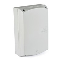
Control panel E1 73RM E1A 73RG E1A
2. REFERENCE TO ILLUSTRATIONS
The given operating and performance features can only be
guaranteed with the use of DITEC accessories and safety
devices.
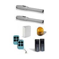
2.1 Standard installation references (fig. 1)
[1] Radio
[2] Flashing light
[3] Key selector
[4] Geared motor + control panel
[5] Photocells
[6] Rubber edge - sensitive edge
[7] Opening and closing stop
[8] Connect power supply to an type-approved omnipole
switch with a contact opening gap of no less that 3 mm
(not supplied by us)
Connection to the grid is made with independent channels
and separated from the connections to the control and
safety devices.
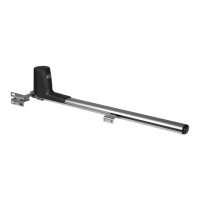
2.2 Geared motor references (fig. 3)
[9] Motor
[10] Casing
[11]
Manual release
[12] Control panel
[13] Limit-switch spring
[14] Pinion
[15] Internal photocell
[16] Courtesy light (optional)
[17]
BATK7 battery kit (optional, only CROSS5EH-7EH)
3. INSTALLATION
Unless otherwise specified, all measurements are expressed
in millimetres (mm).
3.1 Preliminary checks
Check the stability of the wing (derailing and lateral falls) and
the sliding wheels and that the upper guides do not cause any
friction.
The sliding guide must be securely fixed to the ground for the
full length within the doorway and must have no irregularities
that could hinder the movement of the gate.
The opening and closing stops must be fitted.
Note: make sure that the gate can not exit the sliding guides
and fall.
If the gate has slits, make sure they are covered to prevent
shearing points.
Safety device should be installed at the end of the wing to reduce
the collision force.
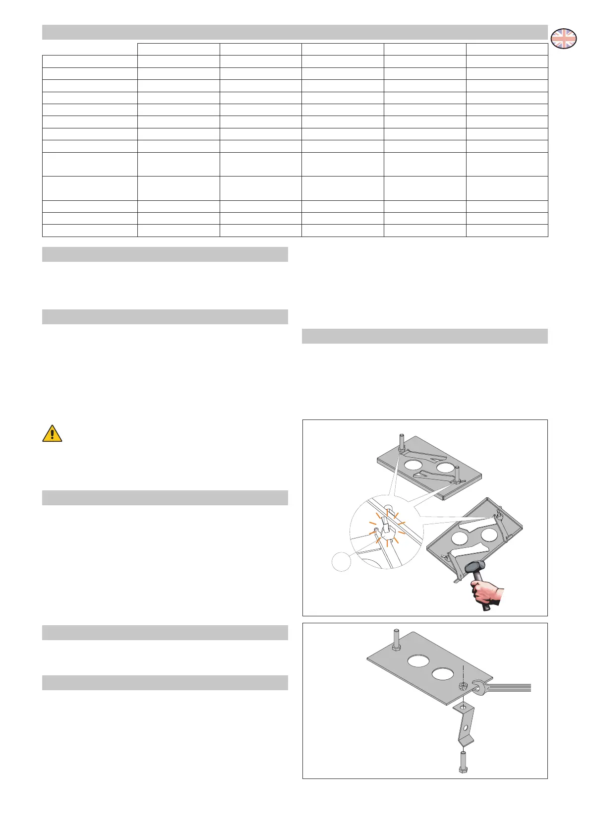
3.2 Base plate position
- First, insert the screws into the base plate blocking them
with a low nut [P], then, fold the tang to avoid displace-
ment.
- Take out the preformed wall anchors with a downward
movement and with the help of a hammer to ensure proper
anchorage to the concrete.
 Loading...