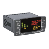
IC100CX
1592022550 Quick reference guide IC100CX GB rel.1.0 03/03/2008 Page 14 di 39
A08 Evaporator
water flow
alarm
(air/water or
water/water
units)
If CO11≠0:
digital input active for AL06;
the alarm signal is disabled for AL04 starting
from the start-up of the evaporator pump.
If CO11=0:
digital input active for AL06.
• If CO11=0
Alarm relay/ open
collector ON.
Buzzer ON.
General alarm icon
lighted.
Flashing “Flow!”
icon.
Code on display.
If the unit is in std-
by or OFF the icon
is on to indicate the
the real state of the
pump and the flow
switch.
• If CO11≠0
Alarm relay/ open
collector ON.
Buzzer ON.
General alarm icon
lighted.
Flashing “Flow!”
icon.
Code on display.
Automatic.
for AL07.
It turns to manual if
the digital inpuct is
active for AL05.
Manual:
for AL07, then
proceed with manual
reset.
A09 Compressor 1
thermal
protection
alarm
Digital input active; bypassed for AL08 upon
start-up of compressor
Open collector / alarm
relay ON.
Buzzer ON.
General alarm icon
lighted.
Alarm code on display.
Manual:
the event expires,
then proceed with
manual reset.
A10 Compressor 2
thermal
protection
alarm
Digital input active Open collector / alarm
relay ON.
Buzzer ON.
General alarm icon
lighted.
Alarm code on display.
Manual:
the event expires,
then proceed with
manual reset.
A11 Condenser
fan thermal
protection
alarm
Digital input active Open collector / alarm
relay ON.
Buzzer ON.
General alarm icon
lighted.
Alarm code on display
Manual:
the event expires,
then proceed with
manual reset.
A12 Defrost error
alarm
Defrost ended for maximum time dF07 with
dF02=1
General alarm icon
lighted.
Only alarm code on
display.
Automatic:
with next proper
defrost cycle.
Proceed with manual
reset.
 Loading...
