IC100CX
1592022550 Quick reference guide IC100CX GB rel.1.0 03/03/2008 Page 19 di 39
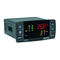
19. CONNECTING DIAGRAM
19.1 Model with 5 internal relays and 1 modulating output (0..10V or 4..20mA)
MF ID1, MF ID2, MF ID5 = multifunction digital inputs
ID3 = high pressure digital input
ID4 = low pressure digital input
RL1 = compressor relay
MF RL2, MF RL3, MF RL4, MF RL5 = multifunction
relays
MF o.c. out = multifunction open collector output (for
external relay)
Pb1, Pb2, Pb3, Pb4 = NTC probe or digital input
Tk = output for external fan speed controller
Analog output = output 0..10V / 4..20mA for external fan
speed module (for condenser fan or modulating
evaporator water pump)
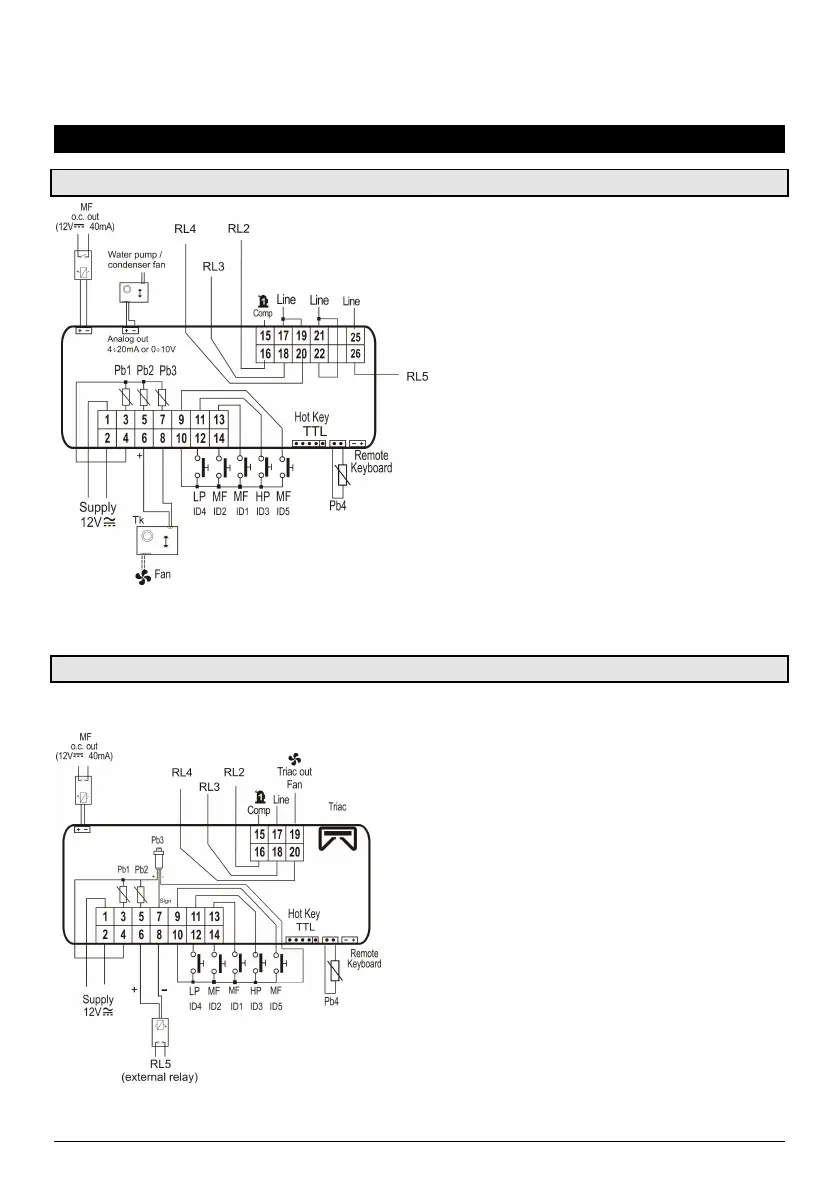
19.2 Model with triac on board and ratiometric pressure trasducer (Pb3)
MF ID1, MF ID2, MF ID5 = multifunction digital inputs
ID3 = high pressure digital input
ID4 = low pressure digital input
RL1 = compressor relay
MF RL2, MF RL3, MF RL4 = multifunction relays
RL5 = output for multifunction external relay
Triac out fan = output for condenser fan
Pb1, Pb2, Pb4 = NTC probe or digital input
Pb3 = ratiometric pressure trasducer
MF o.c. out = multifunction open collector output (for external
relay)
 Loading...