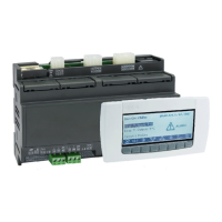
IC100CX
1592022550 Quick reference guide IC100CX GB rel.1.0 03/03/2008 Page 5 di 39
When there is not communication between the keyboard
and the instrument the display visualizes ”noL” (no link
message).
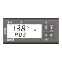
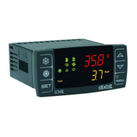
4. DISPLAY VISUALIZATION
Upper digits (red color): configurable by parameter CF36
(PB1, PB2, PB4, Set-point (parameter value)*, working set-
point (real set-point modified from dinamic set-point,
Energy saving or function for units without water storage
tank), Hysteresis, Machine status **)
Lower digits (yellow color): configurable by parameter
CF43 (PB1, PB2, PB3, PB4, Set-point (parameter value)*,
working set-point (real set-point modified from dinamic set-
point, Energy saving or function for units without water
storage tank), Hysteresis, RTC, Machine status **).
*the display visualizes chiller set point when the unit is on
and in chiller mode, heating set point when the unit is on
and in heat pump mode, and OFF when the unit is in
standby.
**the display visualizes OnC when the unit is on and in
chiller mode, OnH when the unit is on and in heat pump
mode, and OFF when the unit is in standby.
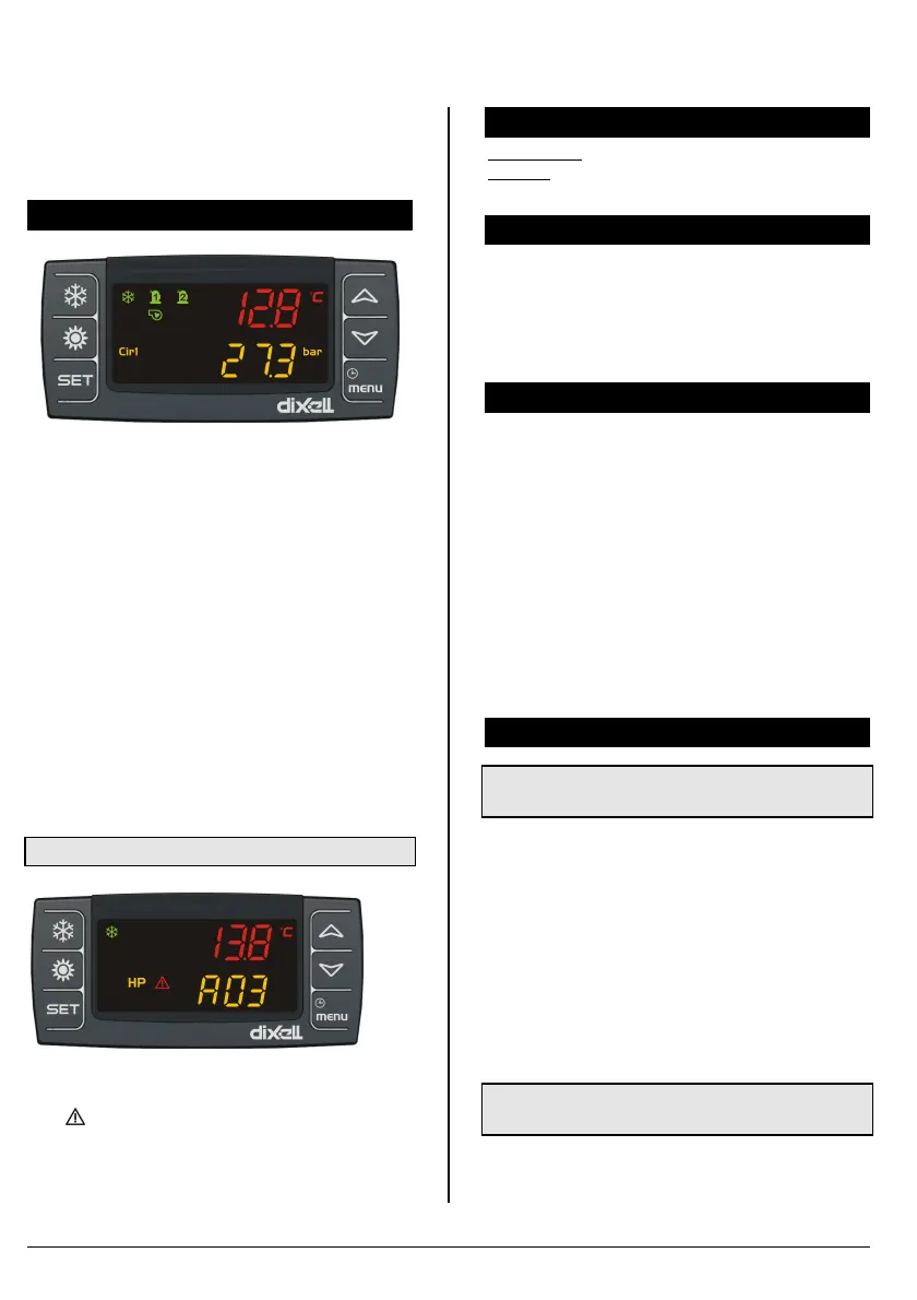
4.1 Alarm visualization
When the instrument detects an alarm, the lower display
shows the alarm code alternated to probe value. The alarm
icon (
) is on flashing.
In case of HIGH PRESSURE alarm (HP), LOW
PRESSURE alarm (LP) or WATER FLOW SWITCH
(Flow!), dedicated icons are on.
5. SILENCING THE BUZZER
Automatically: just after the alarm condition is recovered.
Manually: push and release one of the keys; the buzzer is
stopped even if the alarm is still active.
6. FIRST INSTALLING
After giving power supply to the instrument, the lower
display can show “rtC” alternated to the probe value: it is
necessary to set the clock time.
If the probes are not connected, or they are faulty, the
display shows the corresponding alarm code.
In any case it is possible to proceed with clock setting.
7. HOW TO SET THE CLOCK RTC
1. Push “menu” key for some seconds and wait until
“Hour” label appears.
2. Push “SET”: the hour value starts flashing.
3. Push n or o to change the value. Confirm by
pushing “SET”; after some seconds the controller will
show “Min”.
4. Repeat points 2 and 3 to set other parameters:
Min: minutes (0÷60)
UdAy: day of the week (Sun = Sunday, Mon = Monday,
tuE = Tuesday, UEd = Wednesday, tHu = Thursday, Fri
= Friday, SAt = Saturday).
dAy: day of the month(0÷31)
MntH: Month (1÷12)
yEAr: Year (00÷99)
8. “ HOT KEY” PROGRAMMING
8.1 Download from the Hot Key (previously
programmed) to the Instrument Memory
• The controller has to be not connected to the power
supply
• Insert the Hot Key into dedicated connector
• Connect the controller to the power supply
• The download starts and lasts some seconds.
During this phase the whole regulation is locked and the
“dOL” message is flashing.
“End “ message will appear if the programming result is
good, after 15 sec. the regulation automatically restarts
If “Err” message appears the operation has given bad
result. Turn the controller off and then on again to repeat
the operation or restart the normal regulation.
8.2 Upload the Parameter from the Controller to
the Hot Key
The instrument has to be connected to the power supply:
1. Insert the Hot Key
2. Push “menu”
 Loading...