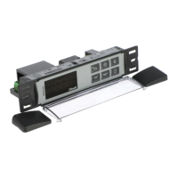
11.1 CUT OUT
11.2 STEEL FINISHING MOUNTING
1
1
2
23
3
4
4
RG-LX gascke
(optional)
12. ELECTRICAL CONNECTIONS
The instruments are provided with screw terminal block to connect cables with a cross section up to
2,5 mm
2
for the digital and analogue inputs. Relays and power supply have a Faston connection
(6,3mm). Heat-resistant cables have to be used. Before connecting cables make sure the power
supply complies with the instrument’s requirements. Separate the probe cables from the power supply
cables, from the outputs and the power connections. Do not exceed the maximum current allowed on
each relay, in case of heavier loads use a suitable external relay.
N.B. Maximum current allowed for all the loads is 20A.
12.1 PROBE CONNECTION
The probes shall be mounted with the bulb upwards to prevent damages due to casual liquid
infiltration. It is recommended to place the thermostat probe away from air streams to correctly
measure the average room temperature. Place the defrost termination probe among the evaporator
fins in the coldest place, where most ice is formed, far from heaters or from the warmest place during
defrost, to prevent premature defrost termination.
13. HOW TO USE THE HOT KEY
13.1 HOW TO PROGRAM A HOT KEY FROM THE INSTRUMENT (UPLOAD)
1. Program one controller with the front keypad.
2. When the controller is ON, insert the “Hot key” and push
key; the "uPL" message appears
followed a by flashing “End”
3. Push “SET” key and the End will stop flashing.
4. Turn OFF the instrument remove the “Hot Key”, then turn it ON again.
NOTE: the “Err” message is displayed for failed programming. In this case push again
key if you
want to restart the upload again or remove the “Hot key” to abort the operation.
13.2 HOW TO PROGRAM AN INSTRUMENT USING A HOT KEY
(DOWNLOAD)
1. Turn OFF the instrument.
2. Insert a programmed “Hot Key” into the 5 PIN receptacle and then turn the Controller ON.
3. Automatically the parameter list of the “Hot Key” is downloaded into the Controller memory,
the “doL” message is blinking followed a by flashing “End”.
4. After 10 seconds the instrument will restart working with the new parameters.
5. Remove the “Hot Key”..
NOTE the message “Err” is displayed for failed programming. In this case turn the unit off and then on
if you want to restart the download again or remove the “Hot key” to abort the operation.
14. ALARM SIGNALS
Compressor output acc. to par. “Con” and “COF”
Maximum temperature alarm
Minimum temperature alarm
Condenser high temperature
It depends on the “Ac2” parameter
Condenser low temperature
It depends on the “bLL” parameter
Compressor and fans restarts
Serious external alarm (i1F=bAL)
Pressure switch alarm (i1F=PAL)
Alarm output ON; Other outputs unchanged;
Defrosts according to par. “IdF” Set real time clock
Real time clock board failure
Alarm output ON; Other outputs unchanged;
Defrosts according to par. “IdF” Contact the service
14.1 ALARM RECOVERY
Probe alarms P1”, “P2”, “P3” start some seconds after the fault in the related probe; they automatically
stop some seconds after the probe restarts normal operation. Check connections before replacing the
probe.
Temperature alarms “HA”, “LA” “HA2” and “LA2” automatically stop as soon as the temperature
returns to normal values.
Alarms “EA” and “CA” (with i1F=bAL) recover as soon as the digital input is disabled.
Alarm “PA” (with i1F=PAL) recovers only by switching off and on the instrument.
14.2 OTHER MESSAGES
In programming mode: none parameter is present in Pr1
On the display or in dP2, dP3, dP4: the selected probe is nor enabled
15. TECHNICAL DATA
Housing: self extinguishing ABS.
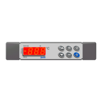
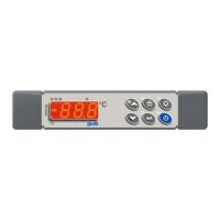
Case: facia 38x185 mm; depth 48mm
Mounting : panel mounting in a 150x31 mm panel cut-out with two screws.
∅ 3 x 2mm.
Distance between the holes 165mm
Protection: IP20; Frontal protection: IP65 with frontal gasket mod RG-L. (optional)
Connections: Screw terminal block
≤ 2,5 mm
2
heat-resistant wiring and 6,3mm Faston
Power supply: 230Vac or. 110Vac or 24Vac
± 10%
Power absorption: 5VA max.
Display: 3 digits, red LED, 14,2 mm high.
Display: 3 digits, red LED, 14,2 mm high; Inputs: Up to 4 NTC or PTC probes.
Digital inputs: 2 free voltage
Relay outputs: Total current on loads MAX. 20A
compressor: relay SPST 20(8) A, 250Vac
light: relay SPST 8 or 16(3) A, 250Vac
fans: relay SPST 8(3) A, 250Vac
defrost: relay SPST 8(3) A, 250Vac
Other output : buzzer (optional)
Serial output : TTL standard; Communication protocol: Modbus - RTU
Data storing: on the non-volatile memory (EEPROM).
Internal clock back-up: 24 hours (only for model with RTC)
Kind of action: 1B; Pollution grade: 2;Software class: A.;
Rated impulsive voltage: 2500V; Over voltage Category: II
Operating temperature: 0÷60 °C; Storage temperature: -30÷85 °C.
Relative humidity: 20÷85% (no condensing)
Measuring and regulation range: NTC probe: -40÷110°C (-40÷230°F);
PTC probe: -50÷150°C (-58÷302°F)
Resolution: 0,1 °C or 1°C or 1 °F (selectable); Accuracy (ambient temp. 25°C): ±0,7 °C ±1 digit
16. CONNECTIONS
16.1 XW60LS – DRY CONTACTS
Supply: 120Vac or 24Vac: connect to terminals 11-12
The X-REP output is optional
16.2 XW60LS – DIRECT CONNECTIONS OF LOAD
Supply: 120Vac or 24Vac: connect to terminals 5-6
The X-REP output is optional
1592027350 XW60LS RTC GB r1.0 18.03.2015 XW60LS 4/5
 Loading...