66
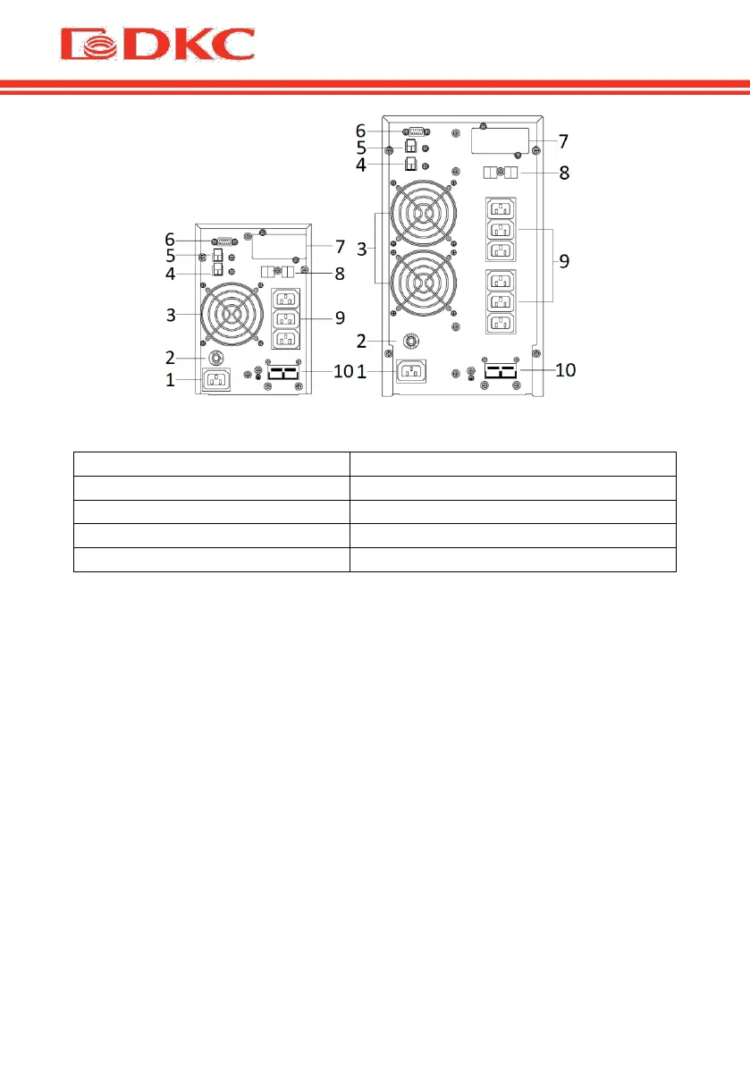
Figure 3 – Rear panel of the UPS SMALLT1 and SMALLT2 / SMALLT3
7 - slot for SNMP/AS400 board
5 - EPO (Emergency Power Off)
Table 5. Description of rear panel of the UPS
1. Input connection
One end of the power cable is connected to the UPS via the IEC C13 / C19
connector (the input in Figure 6), the opposite end of the power cable is
connected to the mains socket..
2. Output connection
Connect loads directly to the UPS output sockets. Be aware of not exceeding
the maximum power of the UPS.
Note:
The figure is for reference only. Due to the technology upgrading and
development, the real unit might be different from the figure.