6005-065-M-12-17
16
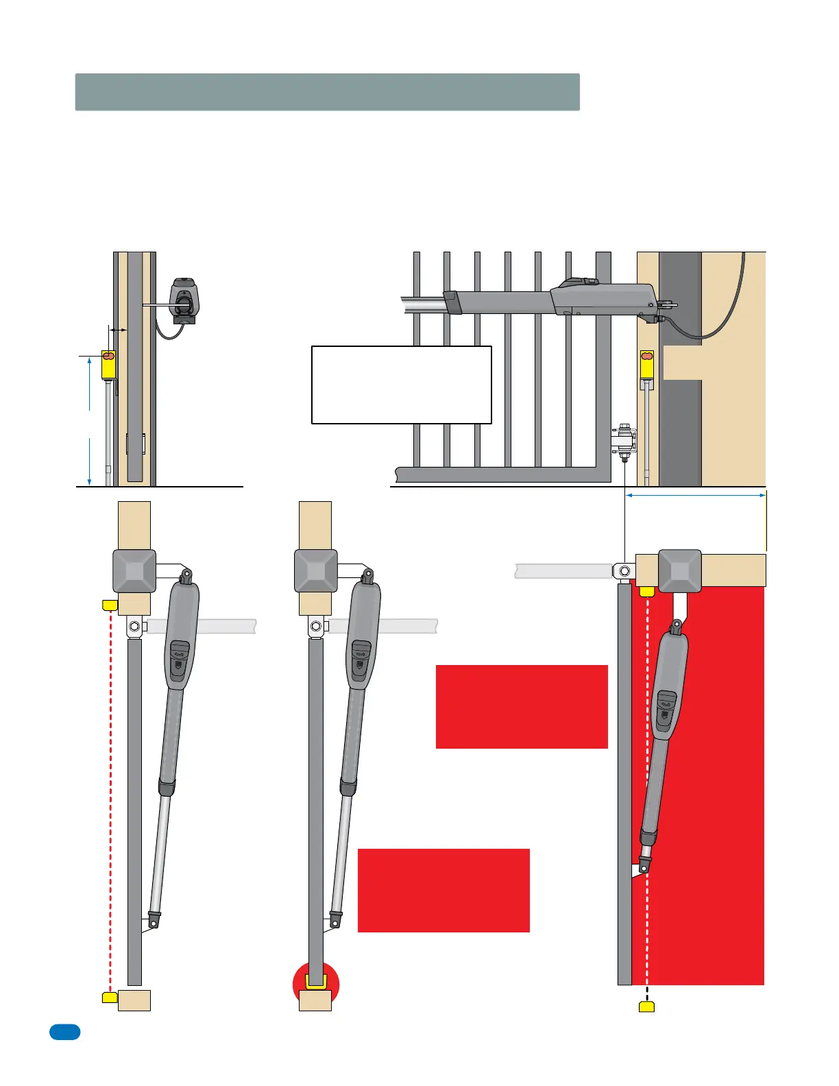
OPEN Photo Sensor
Side View
UL sensor mounted
just below actuator
arm cable.
or less
5”
Gate Closed
If this space is less than 16
inches, entrapment protec-
tion is required in this area.
Potential
Entrapment
Area
Top View
External Entrapment Protection Devices:
In addition to the inherent reversing sensor system, this operator’s control board has a 6-pin UL 325 terminal for the connection of photo
sensors-Type B1 and/or reversing edge-Type B2 entrapment protection required by UL 325 standards. An external entrapment protection
device MUST be installed or the operator will NOT function. Install these devices where the risk of entrapment or a safety hazard exists
while the gate is moving. Specific installations will vary. See the 115 VAC control box Wiring/Owner’s manual OR Solar control box
Wiring/Owner’s manual to wire entrapment protection devices.
Closing-Direction Photo Sensor
Opening-Direction
Opening Gate
Closing Gate
Potential Entrapment Area:
If the CLOSING gate could cause
an entrapment, then installation
of a MONITORED entrapment
protection device is REQUIRED.
Potential Entrapment Area:
If the OPENING gate could cause
an entrapment, then installation
of a MONITORED entrapment
protection device is REQUIRED.
Monitored Photo Sensor
Monitored
Photo Sensor
CLOSE Photo Sensor
Side End View
Entrapment Protection Device Locations
IMPORTANT: Photo sensors must
use Normally Closed (NC) contacts
with the beam set for light operate
(relay activated when beam is not
obstructed).
Closed Gate
Open Gate
Closed Gate
Closed Gate
Open Gate
Top View
21”
Typical
Potential
Entrapment
Area
Monitored
Reversing
Edge
Top View
Closed Gate
Open Gate