6005-065-M-12-17
9
Manual Release
Manual Release
Actuator Arm Assembly
INSTALLATION
Prior to beginning the installation of the swing gate operator, we suggest that you become familiar with the
instructions and illustrations in this manual. This will help insure that your installation is performed in an
efficient and professional manner compliant with UL 325 safety and ASTM F2200 construction standards.
The proper installation of the vehicular slide gate operator is an extremely important and integral part of the
overall access control system.
Check all local building ordinances and building codes prior to installing
this operator. Be sure your installation is in compliance with local codes.
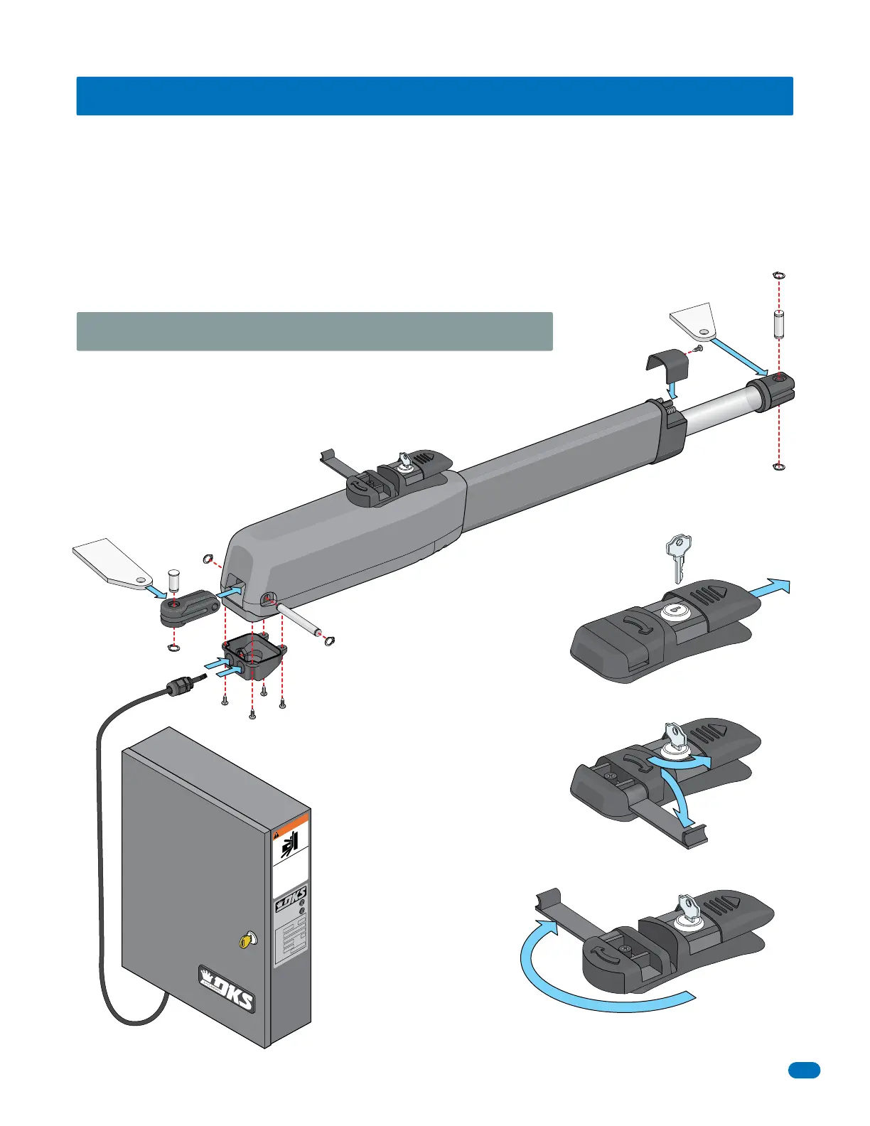
1. Slide door open and insert key.
2. turn key 90° and flip handle out.
3. Rotate handle 180°.
Powered Shaft/Gate can now be manually moved.
Snap ring pliers required for assembly.
TIP: Safety glasses are recommended
when installing snap rings.
Note: Recommend greasing
rear pin and short rod.
6005 Assembly and Manual Release
Rear
Pin
Snap Ring
Electrical Cover
(Gain access to wiring terminal)
Control Box (Sold Separately)
115 VAC OR Solar Power
(Mounted near the 6005)
Wire Connector
(Choose hole)
7-Wire Cable
Hex Hole
on Top
Recessed
Hole on Top
Snap
Ring
Snap
Ring
Snap
Ring
Snap
Ring
Long Rod
Short
Rod
Rear Mounting
Bracket
Front
Mounting
Bracket
Limit
Cover
Limits Adjustment
WARNING
MOVING GATE CAN C
A
US
E
Op
erate
g
ate
o
n
l
y
w
h
en
g
ate ar
ea
i
s
i
n
si
g
h
t
an
d
free
o
f
p
eo
p
l
e and
o
b
st
r
u
c
t
i
o
n
s.
D
o
n
o
t all
o
w
ch
i
l
d
r
en
to
p
l
ay
i
n
g
ate ar
ea
o
r
o
p
erate
g
ate.
Do
n
o
t stan
d
i
n
g
ate
p
at
h
o
r
w
al
k th
r
ou
g
h
p
at
h
w
h
i
l
e
g
at
e
i
s mo
vi
ng
.
Read
o
w
n
er
’
s
ma
n
u
al
an
d
safety
i
n
st
ru
ct
i
o
n
s.
S
ER
IOUS IN
J
UR
Y
O
R
D
EATH
CLASS
CERT
I
FI
E
D
TO
CAN/
CSA
C2
2.
2
NO.
2
47
CONFORMS
T
O
ANSI
/
UL-
32
5
VE
H
I
CU
L
A
R
G
AT
E
O
PE
R
AT
O
R
HP
5
3
3
8
2
MODEL
SERIAL
VO
L
TS PHASE
AMPS
60
Hz
MAX
GA
TE
L
OA
D
DoorK
ing,
In
c
.
,
I
ngle
woo
d
,
C
A
Hinge Placement Note: It’s important to consider hinge placement on a pilaster or a thick wall
when installing the gate. Placing hinges close to the corner can eliminate a potential entrapment
area (See Swing Gate Requirements on page 7).
Powered Shaft