6005-065-M-12-17
19
1
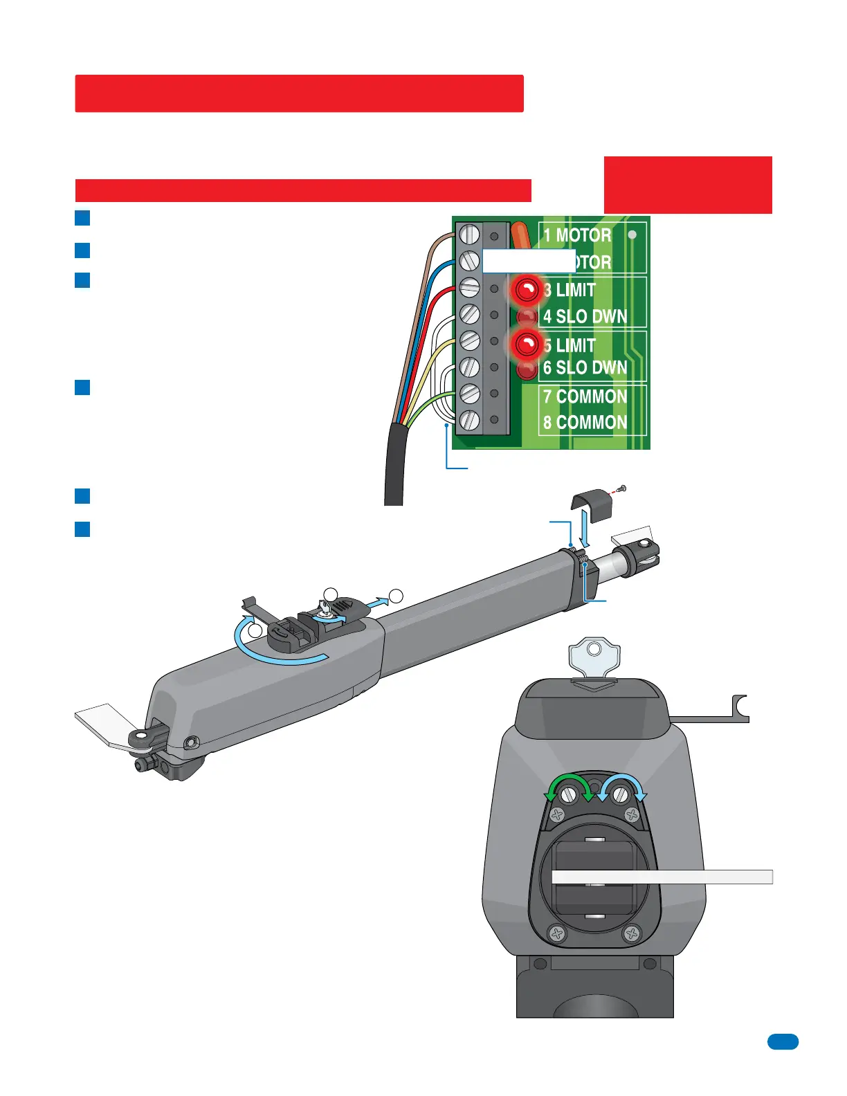
Remove the limit cover with one screw.
Manually release 6005.
A
B
Manually move the gate to the closed position.
adjust CLOSE screw:
Clockwise increases the power shaft distance.
Counter-clockwise reduces distance.
5 LIMIT LED on the circuit board lights up
when CLOSE switch has been activated.
Manually move the gate to OPEN position.
adjust OPEN screw:
Counter-clockwise increases the power shaft distance.
Clockwise reduces distance.
3 LIMIT LED on the circuit board lights up when
OPEN switch has been activated.
C
D
E
F
Limit LEDs
Adjust the secondary 6005 limit sensors if dual actuators
have been installed. DIP-switch SW 1, switch 2 controls
secondary 6005 opening direction. DIP-switch SW 1,
switch 7 MUST be ON when using dual actuators.
When finished setting limits, cycle
operator a few times and re-adjust the
open and close positions if necessary.
This guide is for installers familiar with DoorKing products ONLY. DO NOT use this as your only source to wire, adjust limit
sensors and DIP-switches if you are unfamiliar with this operator. Please refer to the control box manual you are installing for
complete wiring, adjustments and DIP-switch settings for this operator.
Re-lock 6005 and re-install the limit cover.
Notes:
3 LIMIT LED is ON in
OPEN Gate Position.
4 SLO DWN LED will
NOT light during open
cycle.
5 LIMIT LED is ON in
CLOSE Gate Position.
6 SLO DWN LED
WILL light during
close cycle.
Quick Guide for 6005 Limit Sensors
End View
Power to the circuit board must be ON when adjusting the limit sensors.
Limit
Cover
Close Switch
Open Switch
Limit Adjustments
Manual Release
CLOSE
Adjustment
OPEN
Adjustment
+
+
-
-
Operator
Cable
Factory Wired Jumpers
2
3
Factory wired jumpers MUST
remain connected as shown.
SLO DWN LEDs are always lit.
IMPORTANT: The operator MUST OPEN GATE upon initial power up
and OPEN command.
If the operator closes gate after giving first open command, shut off
power and reverse DIP-switch SW1, switch 1 setting otherwise
operator will NOT function correctly.