OBU Manual
Version 3.0 August 27, 2020 15
4 Installing the OBU
The OBU is designed for a voltage range of 8 V – 32 V DC and must therefore be used inside
this voltage range. If your on-board network can generate higher voltages (e.g. jump-starting
from an external power source or from additional stronger power generators in the vehicle),
the OBU must be disconnected from the on-board network for the duration of the over-
voltage.
The OBU can be installed in two ways:
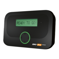
Permanent installation:
The OBU is connected permanently to the vehicle electrical system.
Figure 6: Permament installation on the windshield
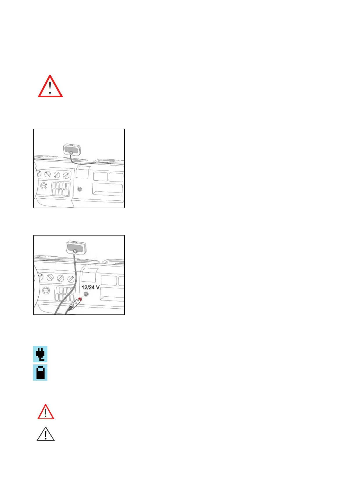
Flexible installation:
The OBU is connected to the cigarette lighter socket.
Figure 7: Flexible installation on the windshield
The status of the power supply is visible on the display:
Power supply via connection to the vehicle electric system.
Power supply via rechargeable battery. Please, consider the battery loading status during driving.
4.1 Positioning the OBU on the windshield
All times mount the OBU in such a way that the driver‘s field of vision is not impaired!
Please, consider different windshield characteristics, e.g. metalized, unmetallized areas, depend-
ing on the kind of windshield in your vehicle. Check the windshield characteristic in the