CellCom‑LTE
Programming and Installation Guide Digital Monitoring Products
13
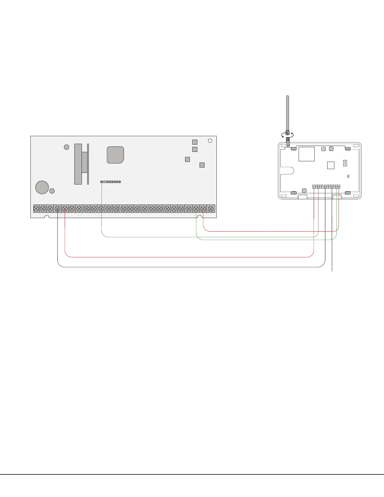
Honeywell Vista 20 Panel Wiring
1. Connect the communicator’s Z1 (zone 1) terminal to output 17 on the control panel.
2. Connect the communicator’s O1 (output 1) terminal to the control panel’s keyswitch or arming zone.
3. Connect the T (tip) terminal on the communicator to terminal 23 on the control panel.
4. Connect the R (ring) terminal on the communicator to terminal 24 on the control panel.
5. Power the communicator by connecting its terminal +12V to terminal 5 on the control panel.
6. Connect the communicator’s GND (ground) terminal to terminal 4 on the control panel.
PROG
B
R
RESETLOAD
+DC- Z1
Z2 Z3
G
T
R
+Z4-
O1 O2
CellCom-LTE-V
1 2 3 4 5 6 7 8 9 10 11 12 13 14
15
16 17 18 19
20
21 22 23 24
25
Honeywell Vista 20 Series
OUTPUT 17
Connect to any
keyswitch or arming
zone.
Figure 12: Vista 20 Series Control Panel to CellCom