LCD Keypad Installation Guide 3
Keypad Bus Monitor
For listed re protective systems, the 893A Module or 277 Trouble Sounder must be
installed in the XR100/XR500 Series or XR150/XR350/XR550 Series control panel to
monitor the keypad bus and sound an audible trouble whenever the keypad bus fails
to operate. Refer to the 893A Module Installation Sheet (LT-0135) or 277 Trouble
Sounder Installation Sheet (LT-1304).
Card Readers
When a proximity credential is presented to an internal or external reader, a beep
tone is heard and the Power and Armed LEDs blink. This provides both an audible and
visual acknowledgement of the credential read.
Internal Access Control Reader
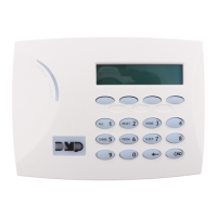
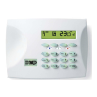
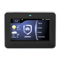
The 7063/7063A, 7073/7073A, and 7163/7173 keypads provide a built-in proximity
card reader designed to read DMP/HID 1300 Series proximity credentials.
Note: For listed access control applications, the keypad must be installed within
the protected area.
External Access Control Reader
To accept Wiegand data input from other external card readers, connect a
12 VDC external reader to the 7073/7073A/7173 keypad. Connect the Red and Black
power wires from the reader to the power wires from the panel. These connect in
parallel with the keypad power wires. Connect the Reader (Data 1) wire to the White
wire on the 5-wire keypad harness. Connect the Reader (Data 0) wire to the Green/
White wire on the 5-wire keypad harness. See Figure 2.
1K EOL
1K EOL
1K EOL
1K EOL
Green/White – Connect Reader Data 0
White – Connect Reader Data 1
Orange – Door Strike Normally Open
Gray – Door Strike Common
Violet – Door Strike Normally Closed
Yellow/White
White/Yellow
Orange White
White/Orange
Red/White
White/Red
Brown/White
White/Brown
Black – Ground
Green – Receive Data
Yellow – Send Data
Red – Keypad Power
– Zone 4
– Zone 3
– Zone 2
– Zone 1
External
Reader/
Door Strike
7073/7073A
7173 Keypads
All Keypads
Zones
1 through 4
7070/7070A,
7073/7073A,
and 7170/7173
Keypads
Surface and Backbox
Mounting Holes
Combined 4-square
and 3-gang switch box
Mounting Holes
Keypad Back
Surface and Backbox
Mounting Holes
All zones are supervised and suitable for fire applications
Maximum zone line impedence 100 Ohms
Ground fault detected at 1420 Ohms or less
 Loading...
