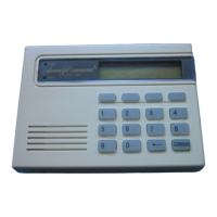
White – Connect Reader Data 1
Orange – Door Strike Normally Open
Gray – Door Strike Common
Violet – Door Strike Normally Closed
Yellow/White
White/Yellow
Orange White
White/Orange
Red/White
White/Red
Brown/White
White/Brown
Black – Ground
Green – Receive Data
Yellow – Send Data
Red – Keypad Power
– Zone 4
– Zone 3 Request to Exit (option)
– Zone 2 Door Contact (option)
– Zone 1 7/0 Panic (option)
To Keypad Bus
External Card
Reader
Figure 2: 12 VDC Reader Wiring
Door Strike Relay Specications
The 7073/7073A/7173 keypads provide one internal programmable Form C single
pole, double throw (SPDT) relay for controlling door strikes or magnetic locks. Three
wires on the 5-wire harness, Violet (N/C), Gray (Com), and Orange (N/O), allow you
to connect devices to the relay. The Form C relay draws up to 15mA of current and
the contacts are rated for 1 Amp resistance at 30 VDC maximum.
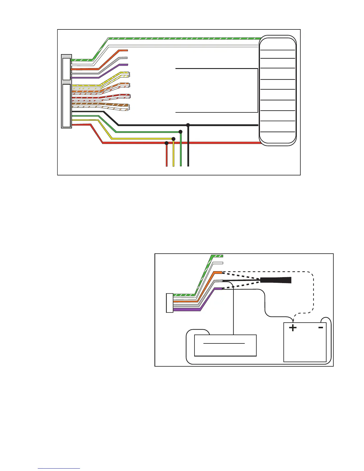
Wiring the 333 Suppressor
One Model 333 Suppressor is
included with the 7073/7073A,
7173 keypads. If the device being
controlled by the relay is connected
to the N/O and C wires, install the
suppressor on the N/O and C wires.
If the device is connected to the
N/C and C wires, install the 333 on
N/C and C wires. Refer to Figure 3.
Door Strike Relay Operation
As soon as the user code sent
from the reader is veried by the
panel, the keypad door strike relay
activates for 5 seconds. During this time, the access door connected to Zone 2 must
be opened to start the programmed entry/exit timer and zone Bypass.
Note: The 5-second door strike is programmable in the panel when the keypad is used
on a XR100/XR500 Series or XR150/XR350/XR550 Series panel. Refer to the panel
programming guide.
Model 333
Supressor
Common
– +
Magnetic Door Lock
DMP 502 or 505
Power Supply
Normally Open
Green/White – D0
White – D1
Orange – N/O
Gray – C
Violet – N/C
N/O
C
N/C
Normally
Closed
Keypad
5-Wire Harness
Figure 3: 5-wire Harness/Suppressor Installation