23 DOALL INSTRUCTION MANUAL
OPERATION
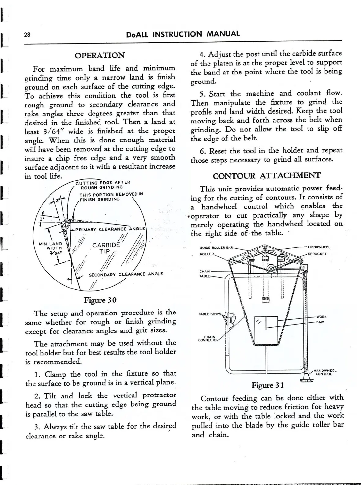
For maximum band life and minimum
grinding time only
a
narrow
land is finish
ground
on
each surface of the cutting edge.
To achieve this condition the tool is first
rough ground
to
secondary clearance and
rake angles three degrees greater than that
desired in the finished tool. Then
a
land
at
least 3/64" wide is finished
at
the proper
angle. When this is done enough material
will have been removed
at
the cutting edge
to
insure
a
chip free edge and
a
very smooth
surface adjacent
to
it
with
a
resultant increase
in tool life.
CUTTING EDGE AFTER
ROUGH GRINDING
THIS
PORTION REMOVED IN
FINISH GRINDING
Figure 30
The setup and operation procedure is the
same
whether for rough
or
finish grinding
except for clearance angles and grit sizes.
The attachment may be used without the
tool holder but for best results the tool holder
is recommended.
1. Clamp the tool in the fixture
so
that
the surface
to
be ground is
in
a
vertical plane.
2. Tilt and lock the vertical protractor
head
so
that the cutting edge being ground
is parallel
to
the
saw
table.
3. Always tilt the
saw
table for the desired
clearance
or
rake angle.
4. Ad
ust
the post until the carbide surface
of the platen is
at
the proper level
to
support
the band
at
the point where the tool is being
ground.
5. Start the machine and coolant flow.
Then manipulate the fixture
to
grind the
profile and land width desired. Keep the tool
moving back and forth
across
the belt when
grinding. Do
not
allow the tool
to
slip ofli
the edge of the belt.
6. Reset the tool
in
the holder and repeat
those steps necessary
to
grind all surfaces.
CONTOUR ATTACHMENT
This
unit
provides automatic power feed-
ing for the cutting of
contours.
It
consists of
a
handwheel control which enables the
-operator
to
cut
practically any shape by
merely operating the handwheel located
on
the right side of the table.
‘
GUIDE ROLLER BAR
A
mnnwucct
O
ROLLER
O #3’ E.‘
.
O
V
spnocxcr
o
7“
o
I I
CHAIN
°
TABLE
_____
~ : :
' 1 I I I '5
E I E: I
I I :5 "I
: I ; g I
_.
;_:__-;_
.,,.
.K
L-_—' I
I
I
mat:
smes
'
I
/
.L..—wom<
I
'/
_::._- SAW
._.._—
.
I I
I
CHAIN
/r
I
countcrore
I ;
-
1
| I
- I
I
"I
‘I
\
:'
)3
'
HANDWHEEL
CONTROL
.
Figure 3 1
Contour feeding
can
be done either with
the table moving
to
reduce friction for heavy
work,
or
with the table locked and the work
pulled into the blade by the guide roller bar
and chain.