21
3. ASSEMBLY
ENGLISH
Fig. 5
Fig. 6
Fig. 7
Fig. 4
A
C
B
D
E
F
Fig. 8
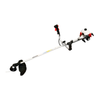
Asta rigida
Long shaft
Attacco rapido
Quick coupling
Albero fl es si bi le
Flexible shaft
3. ASSEMBLY
3.1 Assembly
Make sure that all parts have been assembled cor rect ly
before start ing to work.
3.1.1 Models with rigid shaft
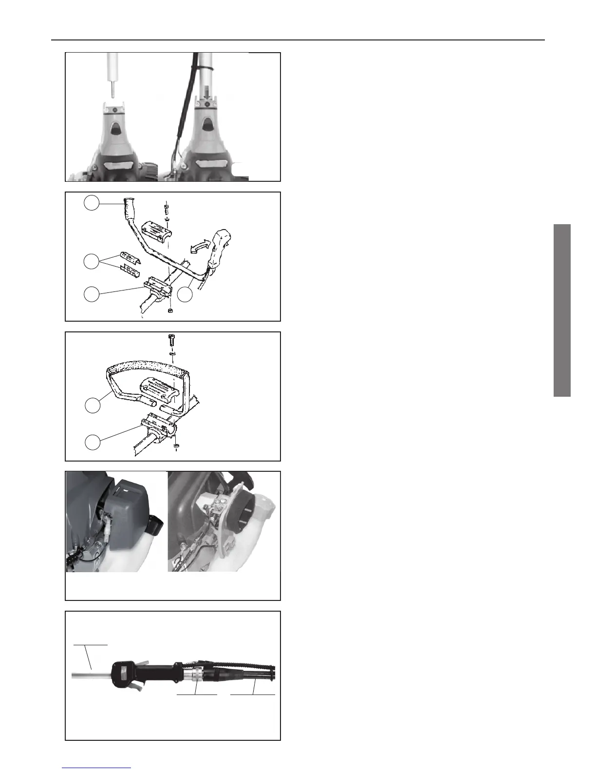
Rod-engine: (Fig. 4). After orienting the rod, connect it
to the en gine by inserting it in the hole in the clutch case.
In order to make sure that the rod has been in sert ed
correctly, check that the red line on the label lines up
with the profi le of the rod retainer jaws.
At this point, lock the rod in place in such way that it
cannot be removed from the engine and screw down
the two screws in the jaws.
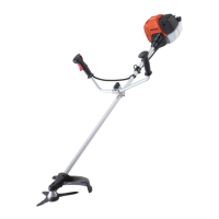
Handle-bar: (Fig. 5). Proceed as follows to lock the
handle-bar securely to the rod: insert the two drilled
plate half-bearings A be tween the handle-bar support C
and the handle-bar pipe B, then take the handle-bar B
and position it so that it can be gripped with the con trol
handle with the accelerator cable in your right hand and
the simple grip D in your left hand. After positioning the
handle-bar B on the cross C, lock it in place with the
cross cover and the four respective fi xing screws.
Before fi xing the handle-bar in place, make sure it is
fastened so that your arms and wrists are fl exed slight ly
in normal work position. If you work in such way that
only your wrists are fl exed and your arms are straight,
the force required may be ex ces sive, es pe cial ly on your
right hand, which is un der constant strain by the need
to continuously work the accelerator trig ger.
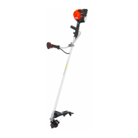
Vibration-damping grip: (Fig. 6). Position the vi bra tion-
damping grip E in the cross F by keeping the long er
part facing left (this serves as a protective barrier dur ing
operation that prevents in vol un tary contact of your body
with the cutting accessory). Before de fi n i tive ly tight en ing
the fi xing screws, adjust it in a position that per mits the
ergonomic use of the machine.
Then defi nitively screw down the fi xing screws.
Connection of the gas control acceleration cable for
models with rigid shaft: (Fig. 7). There is a gas control
cable that leaves the accelerator handle. This cable has
a threaded terminal at its end, and there are two nuts
screwed into the terminal. Take the gas con trol cable
and insert one end into the swivel for the con trol of the
carburetor butterfl y valve. Then position the thread ed
ter mi nal into the respective housing in the nylon cylinder
cover, mak ing sure to pass the steel ca ble be neath the
respective track. Then fasten the thread ed ter mi nal to
the cylinder cover by work ing on the nuts. Then adjust
the threaded terminal in order to elim i nate all slack be-
tween the cable and the sheath in order to en sure cor rect
and progressive acceleration. This threaded ter mi nal
has been built to CE standards and serves to prevent
un de sired acceleration of the machine if the control is
ever ac ci den tal ly contacted. Then connect the ground
cable’s eyelet terminal to one of the four fi xing screws
on the cyl in der cover that sup ports the clutch case and
connect the ground cable’s female faston to the male
faston com ing from the coil. In models equipped with
handle-bars, pass the gas control cable unit inside the
re spec tive lat er al housings in the cross, and the two
cable guides po si tioned on the rod in order to make
sure that the gas con trol unit is fi tted as closely to the
machine as possible.