29
6. MAINTENANCE
ENGLISH
Fig. 31
Fig. 35
1
2
3
4
5
6
7
8
9
10
Fig. 32
2
9
7
6
5
4
3
8
Fig. 33
Fig. 34
6.2 Routine maintenance
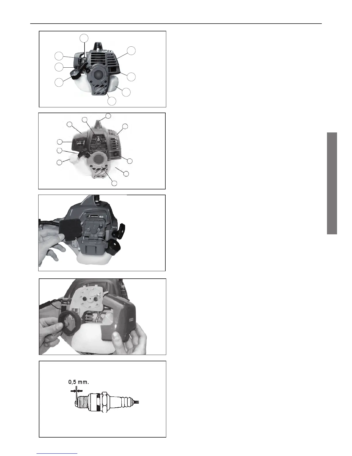
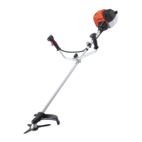
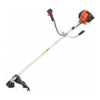
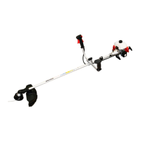
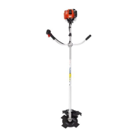
Description of engine parts (fi g. 31 and fi g. 32):
1) Spark-plug cover
2) Cylinder protection
3) Muffl er
4) Tank
5) Starting case
6) Tank cap
7) Starting grip
8) Carburetor
9) Air cowling
10) Decompressor
Maintenance operations to be performed by the
operator:
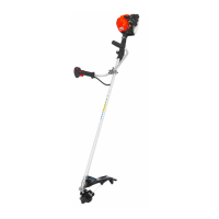
Air fi lter. The air fi lter is positioned inside the carbure-
tor’s red cowling and serves to withhold the dust in the
combustion air sucked in. In order to dis as sem ble the
air fi lter, press the tang positioned beneath the fi lter
cap. Every time the machine is used, the air fi lter and
the cowling must be cleaned using petrol and a brush
and then dried. Clogged air fi lters can cause loss es in
engine power, increased fuel consumption, and make
starting diffi cult (Fig. 33-34).
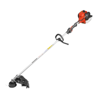
Spark-plug. The spark-plug must be thoroughly cleaned
every 25 hours and all carbon deposits must be re moved.
The gap between the electrodes must be checked and
adjusted if necessary to 0.5 mm (Fig. 35). Change the
spark-plug if the electrodes are corroded or burnt. We
recommend using CHAMPION type spark plugs. A fouled
spark-plug makes the com bus tion of the mixture irregular
and can even prevent the starting of the machine. Spark-
plug fouling can be caused by incorrect carburetion, an
incorrect oil-petrol ratio in the mixture, a clogged air fi lter,
or work con di tions with reduced loads.
Screws and nuts. At least once every 25 working hours,
check and tighten all the fi xing screws and nuts.
Muffl er. At least once every 50 working hours, dis as -
sem ble the muffl er from the cylinder, and scrape away
the carbon deposits from the muffl er’s exhaust pipe,
making sure that no deposits fall into the cylinder.
Clutch. At least once every 50 working hours, use a
brush and petrol to clean the clutch and the case, then
dry thoroughly. Centrifugal clutch begins sticking to the
case at around 3000 ÷ 3500 rpm. Effi cient adhesion of
the jaws occurs above 5000 rpm; we recommend work-
ing by keeping the accelerator open to the maximum
because prolonged use at lower rpm causes the slip ping
of the clutch and premature wear on the jaws.
Bevel gear pair. Grease the bevel gear pair every 25
working hours by unscrewing the screw that serves as
a cap positioned laterally on the bevel gear pair case
and inject the grease using the appropriate pres su rised
syringe until it is full and then screw the screw back
down. We recommend using grease suited for high
tem per a tures of be tween 120° and 170 °C (Fig. 36).