EasyManua.ls Logo

DOM ENiQ AccessManager - Page 16

Default Icon
72 pages
Print Icon
To Next Page IconTo Next Page
To Previous Page IconTo Previous Page
Loading...
ENiQ® Wall Readers & Terminals
_____________________________________________________________________________________
16
The terminals are occupied as follows:
No.
Marking
Function
1
I1
2 inputs e.g. for door contact or release button
2
GND
3
I2
4
GND
5
Reserve
6
7
12-24V
Voltage supply
Supply voltage
8
GND
Voltage supply
9
PoE
Power over Ethernet
10
PoE
11
RD-
Ethernet transmission and receive paths
12
RD+
13
TD-
14
TD+
15
Ö
Output
(changeover contact) actuator
16
C
17
S
18
RxD
Connection
Reader
control unit
Reader

Reader
19
TxD
20
GND
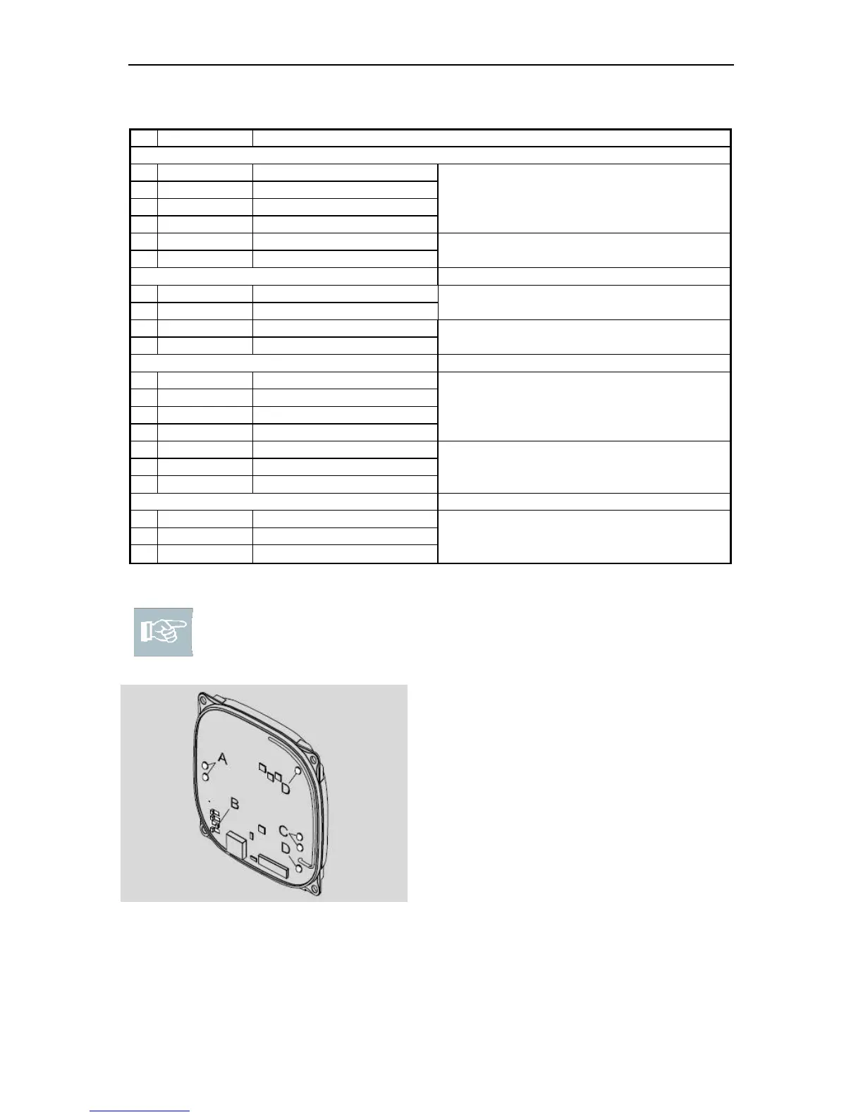
Please note! There are DIP switches and LEDs on each unit. The
required operating mode is set using the DIP switches. Always adjust the
DIP switches when the units are de-energised.
A: Status LEDs for reader (cf. page 22):
Only light up on the DOM device
with controller, not on the connected
ENiQ
®
Passive Reader or reader of
the ENiQ
®
Module
Reader.
B: DIP switch operating mode C:
Status LEDs power, wireless
operation D: LED Access control
Fig. 8: DIP switches and LEDs

Table of Contents