6
EN
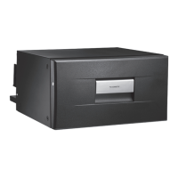
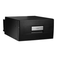
General Information Refrigerators
q
w
re
t
y
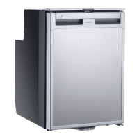
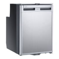
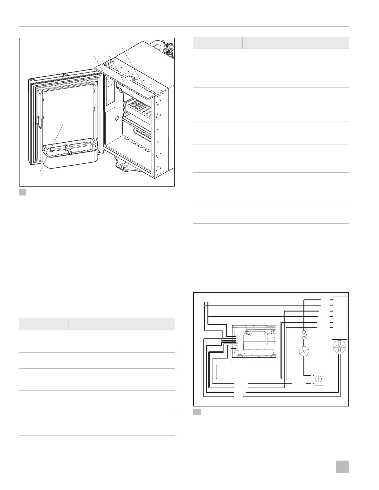
3 General CRX Component Locations (Front View)
q
Door Assembly
r
Vent Cover
w
Shelving and Racks
t
NTC Sensor
e
Thermostat Assembly
y
Handle Assembly
I
The NTC sensor is mounted on the interior of the
unit toward the le side of the refrigerator.
4.4 General Refrigerator
Terminology
The following table defines some of the terms that are
typically used when dealing with refrigerator units.
Term Definition
Capillary Tube
Refrigerant liquid metering device that
regulates refrigerant flow from the high-
pressure side into the low-pressure side
Capillary Tube
Strainer/Dryer
Filter used to prevent particulate from
entering the refrigerant flow control
Compressor
Component that circulates the
refrigerant necessary for heat exchange
through the coils
Condenser
Heat exchanger section to cool down
and condense incoming refrigerant
vapor into liquid
Condenser Coil
Tubing used to release heat energy from
refrigerant and condense refrigerant
vapor into liquid
Term Definition
Condenser Fan
Fan that circulates air, which helps the
condenser unit function properly
Control Module
Power distribution board and
compressor controller that directs
incoming power to the unit
Load Dump
Board
Component that disconnects the
refrigerator from the truck electrical
system when DC voltage exceeds
32 VDC (reconnection occurs aer the
DC voltage returns to normal)
Locking Wheel
Selector wheel on the refrigerator
handle assembly that can be set to
"normal" or "vent" positions
Negative
Temperature
Coefficient (NTC)
Sensor
Thermistor that allows the refrigerator to
stay within a short range of temperatures
and turn on its cooling cycle when the
temperature starts to rise
Printed Circuit
Board (PCB)
Thin board made of fiberglass,
composite epoxy, or other laminate
material on which conductive pathways
are etched or "printed"
Thermostat
Assembly
Device that controls the cooling system
components and interior temperature of
the refrigerator unit
4.5 Wiring Diagrams
Figures 4 and 5 provide examples of the wiring
specifications for CR and CRX series refrigerators.
I
The wiring specifications for CD series refrigerators
are similar to those for the CR series shown below.
Input DC 12/24 V
+
+
Fan
AC 250 V
Thermostat
PCB
Compressor
Red
Red
Red
Gray
White
White
White
White
Yellow
Yellow
Gray
Black
Black
Black
–
–
6
4
3
White
4 CR Series Wiring Diagram

 Loading...