32
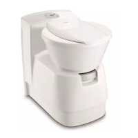
Installing the toilet
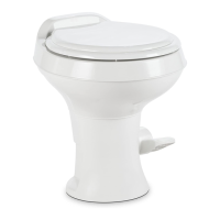
Fig. 32
4.7.1.2 System diagram (CTW 4xxx model with integrated water pump)
12V DC
Supply voltage: 12 V DC
12V connection cable profile : :
min. 0.75 mm²
Toilet control fuse : 7.5 A
(integrated automobile fuse)
Current consumption of the pump : max. 2 A
Control and operator panel
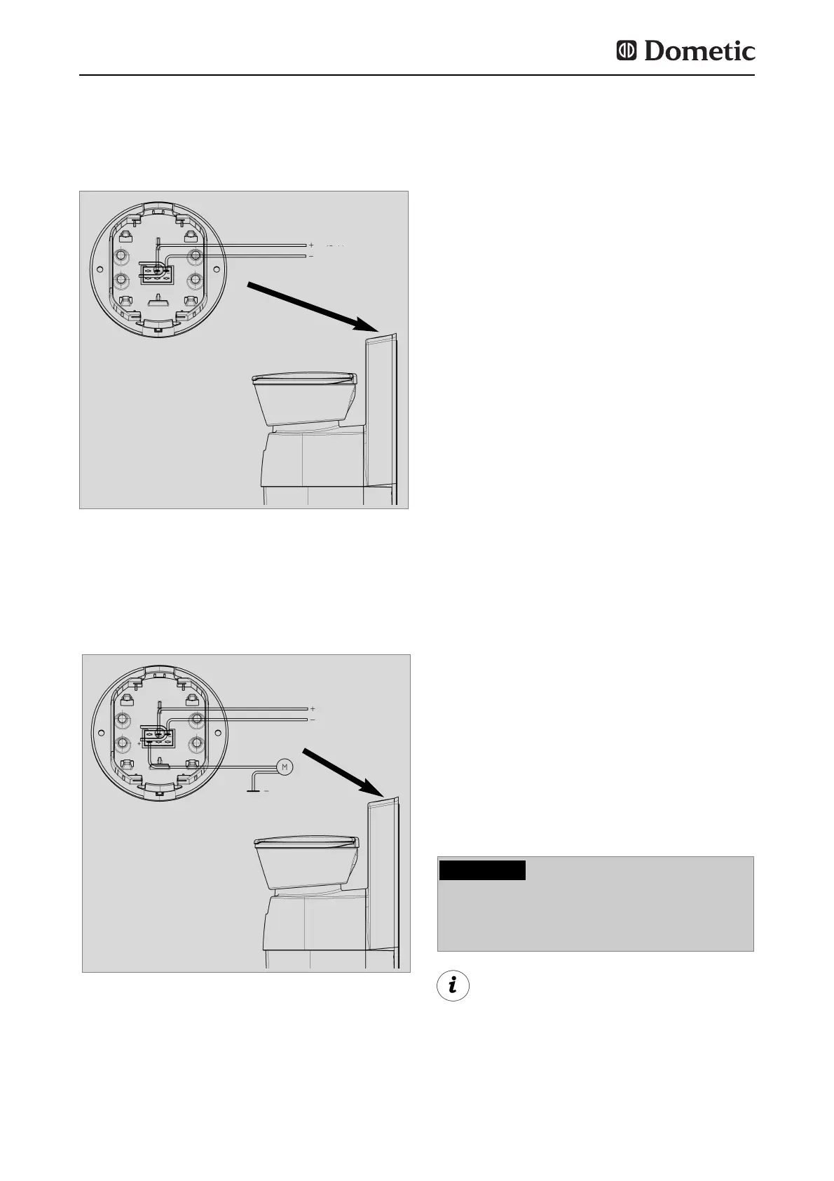
4.7.1.3 System diagrams (CT/CTS/CTLP 4xxx models with external water pump)
Supply voltage: 12 V DC
12V connection cable profile :
min. 1.5 mm²
Toilet control fuse : 7.5 A
(integrated automobile fuse)
Current consumption of the pump : max. 5 A
The external water pump is not included in the
scope of delivery.
The external water pump must not exceed
a nominal power of 60 W (12V/5A).
CAUTION!
Fig. 33
12V DC
Control and operator panel
Pump
 Loading...