EN
10 Operation
Setting the charging program
NOTICE! Damage hazard
• Only use batteries that are suitable for the specified charging voltage.
• Use a small screwdriver to carefully move the DIP switches to the required position.
Select the charging program suitable for the type of house battery used based on the battery manufacturer's specifi-
cations, the information on the charging curves (see chapter Battery charging function on page10), and the tech-
nical data (see chapter Technical data on page23). The specified charging times apply to an average ambient
temperature of 20 °C.
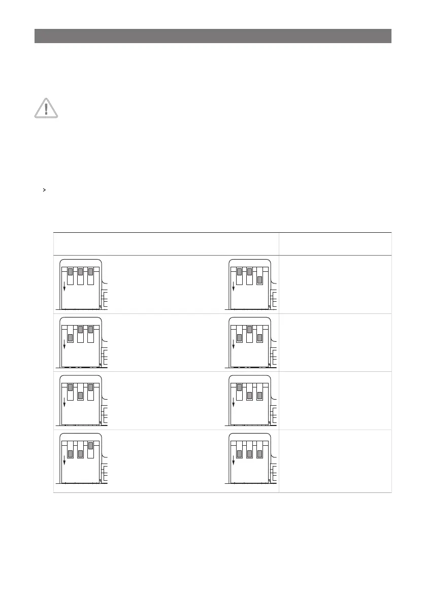
Slide the DIP switches to the position shown in the table below to set the charging program for the respective
type of house battery.
Table 11: Charging curve configuration
DIP switch
position (gray)
Desired charging program DIP switch
position (gray)
Desired charging program
Lead gel batteries (14.2 V)
• U1: 14.2 V (90… 360 min)
• U2: 13.6 V
LiFePO4 batteries (14.4 V)
• U1: 14.4 V (20… 60 min)
• U2: 13.8 V
Lead-acid batteries (14.4 V) or
AGM1 batteries (14.4 V)
• U1: 14.4 V (30… 240 min)
• U2: 13.6 V
LiFePO4 batteries (14.2 V)
• U1: 14.2 V (30 min)
• U2: 13.6 V
AGM2 batteries (14.7 V)
• U1: 14.7 V (30… 180 min)
• U2: 13.6 V
LiFePO4 batteries (14.6 V)
• U1: 14.6 V (20… 60 min)
• U2: 13.8 V
AGM2 batteries with desulfation
(14.7 V)
• U1: 14.7 V (30… 180 min)
• U2: 13.6 V
• U3: 15.7 V
LiFePO4 batteries (14.5 V)
• U1: 14.5 V (30… 90 min)
• U2: –
Performing the system operation check
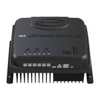
The solar charge controller regulates the charging of up to two batteries: One house battery (B1) and one starting
battery (B2), with priority charging to the house battery.
19
 Loading...