77091 Issue 2 November 2003 35
(5) Slot the vertical mounting bracket
(D) into the square section of the
mounting bracket/base unit and
tighten the height adjustment knob
(E). The horizontal arm may point
towards or away from the conveyor
depending on the application.
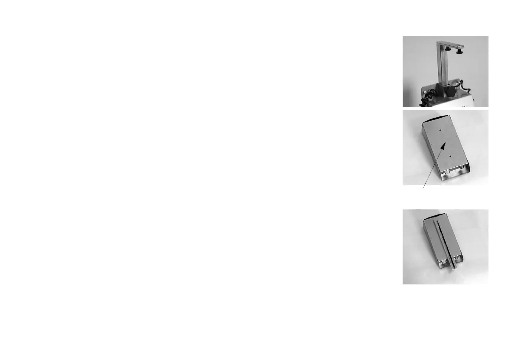
(6) Turn the print head upside down.
On its base are three slide bar
mounting holes. Two of the holes
(not all three) will be used to fix the
print head to the slide bar (F). Screw
the two print head fixing screws (G)
into two adjacent holes. Which two
are depends on the application - in
other words, how far from the edge of
the conveyor the product will be
moving. Do not tighten these screws
yet.
(7) Slot the slide bar (F) onto the print
head by passing the two fixing screws
through two of the “keyhole” cutouts
in the slide bar. Make sure the slide
bar does not extend beyond the
nozzle plate. Tighten the screws.
Slide Bar
Mounting Holes

 Loading...

