Do you have a question about the Doohan iTank and is the answer not in the manual?
Key physical measurements and dimensions of the vehicle.
Key operational capabilities and metrics of the vehicle.
Information related to the structural components and frame of the vehicle.
Details regarding the vehicle's battery specifications and system.
Information about the vehicle's motor and controller specifications.
Essential steps and guidelines before starting vehicle disassembly and part replacement.
Procedure for removing and replacing the external body panels and covers.
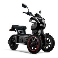
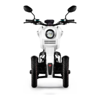
Visual representation and labeling of the vehicle's covering parts for disassembly.
Step-by-step instructions and necessary tools for removing and replacing covering parts.
Process for removing and replacing the vehicle's steering handle assembly.
Diagram illustrating the components of the steering handle system.
List of tools needed for steering handle base disassembly and replacement.
Detailed steps for replacing the steering handle base unit.
Information on servicing and replacing the front wheel and disc brake.
Diagram showing the components of the front wheel and disc brake system.
Required tools and sequence for front wheel and disc brake system maintenance.
Procedure for inspecting and checking the condition of the vehicle's tires.
Instructions for inspecting wheel rims and brake discs for damage or wear.
Procedure for removing and replacing the front disc brake's lower pump.
Steps to remove and replace the front wheel and its disc brake plate.
Procedures for servicing the rear wheel and disc brake system.
Diagram illustrating the rear wheel and disc brake system components.
Tools and sequence for maintenance of the rear wheel and disc brake system.
Process for removing and replacing the rear disc brake's lower pump.
Procedure for removing and replacing the rear splash guard components.
Steps to remove and replace the rear wheel and its disc brake plate.
Information on removing and replacing the seat tank and rear cushion.
Diagram of the seat tank and rear cushion components.
Tools and sequence for disassembling and replacing the seat tank and rear cushion.
Procedure for removing and replacing the vehicle's sitting tank.
Steps for removing and replacing the rear cushion of the vehicle.
Details on the front mechanism assembly and its components.
How the front mechanism is connected to the vehicle frame.
Steps and tools for dismantling and replacing the front mechanism.
Complete procedure for removing and replacing the entire front mechanism.
Detailed diagrams showing exploded views of the front mechanism components.
Procedure for removing and replacing the steering linkage assembly.
Steps for removing and replacing the steering base.
Procedure for removing and replacing the steering knuckle.
Listing and identification of various electrical devices used in the vehicle.
Detailed explanation of the vehicle's electrical components and their functions.
Information about the battery cells, their specifications, and management system.
Description of the vehicle's controller and its role in the electrical system.
Explanation of the electric motor, its type, and operational principles.
Details about the battery charger, connection, and charging process.
Function and application of the DC-DC converter in the vehicle's electrical system.
Description of the brake and kick stand switches and their functions.
Explanation of the Vehicle Control Unit (VCU) and its central control functions.
How to operate the speed control rolling handle for the electric vehicle.
Features and functions of the vehicle's burglar alarm system.
Schematic diagram illustrating the electrical connections and principles of the vehicle.
Guide to diagnosing and resolving common vehicle faults and issues.
Troubleshooting steps for when the vehicle has no electrical power.
Diagnosing issues when the battery is charged but the vehicle remains inoperable.
Procedure for testing and diagnosing the vehicle's controller.
Steps for testing and diagnosing the DC converter.
Troubleshooting steps when the DC converter fails or is damaged.
Diagnosing and resolving issues related to a faulty instrument panel.
Troubleshooting when the motor does not engage after turning the speed handle.
Diagnosing short driving range after a full battery charge.
Troubleshooting when the battery charging process takes an unusually short time.
Diagnosing charger issues when it fails to charge correctly.
Troubleshooting inaccurate battery level display on the instrument panel.
Interpreting the wrench symbol on the instrument panel using the APP for diagnosis.
| Battery | Lithium-ion |
|---|---|
| Max Speed | 45 km/h |
| Brakes | Hydraulic disc brakes |
| Load Capacity | 150 kg |
| Suspension | Front Suspension |