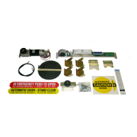
The DC One Sliding Door Retrofit is an automatic sliding door drive assembly designed to upgrade existing sliding door systems. The installation process is estimated to take 2 to 4 hours for one technician.
Function Description
The DC One system replaces the entire existing drive system within the door header, including the motor/gearbox, control, interface, belt, chain, and cables. It integrates with existing sensors, safety beams, and switches, provided they are reused. The system is designed for both single slide and bi-part door configurations.
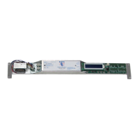
The control unit features a display screen, parameter adjustment knob, and various buttons for programming and testing. It supports multiple operating modes, including Off, One Way, Partial Open, Hold Open, Reset, Emergency Open, Ratchet, Activation, and Night Mode, which can be selected via a multifunction switch. Safety beams are also integrated, activating the door except when in the closed position.
The system includes a lock control feature, allowing for selectable lock voltages (12V or 24V) and monitoring of the lock position. It also supports sensor monitoring for both inner and outer sensors, as well as external safety inputs.
Important Technical Specifications
- Power Input: 120 Volts AC, Single Phase
- Power Consumption: 150W Max
- Secondary Power Supply: 24 Volt, 1A Max.
- Drive Train: Molded Brushed DC Motor with Gear Reduction Assembly
- Control: Microprocessor Controller
- Maximum Door Weight: 400 lbs (200 lbs per panel for bi-part)
- Operating Environment: -4°F to 158°F (-20°C to +70°C), 30% to 85% Relative Humidity
Usage Features
Installation and Setup:
- Header Preparation: Requires disconnecting and removing the existing electrical power, sensors, safety beams, and switches (if not reusing). The entire existing drive system (motor/gearbox, control, interface, belt, chain, cables) must be removed.
- Door Preparation: Involves checking and potentially replacing bottom guides and top rollers. Crucially, manual resistance of the sliding panels (without the belt) should not exceed 8 lb for bi-parts or 4 lb for single slides. Mechanical door stops should be checked and installed if missing.
- Motor and Controller Installation: The DC One motor/gearbox and controller are installed according to enclosed drawings.
- Wiring of Accessories: All accessories, including activation sensors, safety sensors, safety beams, On-Off switch, Emergency Breakout Switch, Electric Carriage Lock, Reduced Opening Switch, and 1-Way Switch, are wired according to provided diagrams.
- Drive Belt and Bracket Installation: After wiring, the drive belt, brackets, and idler pulley are installed. The belt tension should result in approximately 1" to 2" deflection at the center of the longest span.
- Connecting Power: Main power is connected, followed by a factory reset (Sections 12 and 13). A learn cycle is initiated by pressing the TEST button, allowing the door to learn its full open and closed positions.
Programming and Adjustments:
- Program Mode: Accessed by holding the PROGRAM button, pressing RESET once, and continuing to hold PROGRAM until the display changes. Changes are saved by pressing RESET to exit.
- Menu Display: The UP button cycles through menu options. The parameter adjustment knob changes values for each setting.
- Adjustable Parameters:
- Learn Torque: Ranges from 5% to 100%.
- Learn Open Speed: Ranges from 5% to 100%.
- Learn Close Speed: Ranges from 5% to 100%.
- Open Speed: Ranges from 5% to 100%.
- Close Speed: Ranges from 5% to 100%.
- Open Check Speed: Ranges from 5% to 100%.
- Close Check Speed: Ranges from 5% to 100%.
- Boost Speed: Acceleration from a stopped position, ranges from 5% to 100%.
- Open Deceleration: Adjusts transition between open and open check, ranges from 0 to 255. Higher values mean more abrupt changes.
- Close Deceleration: Adjusts transition between close and close check, ranges from 0 to 255. Higher values mean more abrupt changes.
- Open Torque: Ranges from 0% to 100%. Set during auto-learn and readjusted on reset.
- Close Torque: Ranges from 0% to 100%. Set during auto-learn and readjusted on reset.
- Open Check Torque: Ranges from 0% to 100%. Adjustable to ensure the door opens completely without hesitation during the open check cycle.
- Close Check Torque: Ranges from 0% to 100%. Adjustable to ensure the door closes completely without hesitation during the close check cycle.
- Open Check Size: Ranges from 3" to 18".
- Close Check Size: Ranges from 3" to 18".
- Reduced Open Size: Ranges from 12" to 72" in 4" increments.
- Hold Open Time: Ranges from 1 to 30 seconds.
- Door Braking: On/Off for heavy doors.
- Handing: Sets door to right- or left-hand mode.
- Lock Type: Fail Secure or Fail Safe. Auto-detects DC One lock.
- Breakout Polarity: Configures breakout for normally open (NO) or normally closed (NC) contacts.
- Lock Delay: On/Off for electric locks, allows monitoring of lock position.
- Load Factory Defaults: Resets all settings.
- Sensor Monitoring: Selects which sensors to monitor (None, Inner, Outer, Both).
- Language: English or Spanish.
Status and Fault Monitoring:
- Door Position Screen: Displays encoder counts, encoder pulses, status (Activation, Safety, Reduced Open, Breakout), and controller state (Closed, Opening, Open Deceleration, Open Check, Open, Closing, Close Deceleration, Close Check, Boost Mode, Learn Mode, Obstruction).
- Life Cycle Counter: Non-resettable count of total door cycles.
- Trip Cycle Counter: Count of cycles since the last reset.
- Faults Detected: Lists current faults (None, Broken or Loose Belt, Jammed Door, Obstruction Lockout). Obstruction lockout holds the door open after 3 consecutive errors and requires a reset or power cycle.
Sensor Monitoring Schematics:
- IXIO DT1 Sensor Monitoring: Detailed wiring for exterior and interior IXIO DT1 sensors, connecting to J5 and J8. Sensor setup requires "Air: Output Energ / NC" and "Test: ON". Note: Monitoring not required for doors installed prior to November 11, 2017.
- OPTEX i-OneX T Sensor Monitoring: Detailed wiring for exterior and interior OPTEX i-OneX T sensors, connecting to J5 and J8. Sensor settings require "Dip Switch 16 Down (High)" and "Test Input". Note: Monitoring not required for doors installed prior to November 11, 2017.
Maintenance Features
Safety Test and Documentation:
- AAADM Guidelines: After all adjustments, a thorough safety test must be performed according to ANSI A156.10 guidelines and AAADM recommendations. This includes walk tests to verify activation zones (at least 24" out from the door face), hold-open times (at least 1.5 seconds), and smooth closing.
- Daily Safety Check Decal: Must be placed on the door.
- Documentation: All work must be documented, signatures obtained, and the AAADM Owner's Manual provided to the owner/facilities manager.
- Annual Inspection: Door should be inspected by an AAADM certified inspector annually.
- DO NOT USE DOOR: If it fails any safety checks or malfunctions.
Troubleshooting Tips:
- Initial Power Test: Before wiring sensors, apply power and test the door using the TEST button to ensure it opens and closes.
- Status LEDs: Inputs have status LEDs (Power, Control On, Door Lock, Heartbeat, Safety, Outer Sensor, Inner Sensor, Hold Open, Partial Open, One Way, Emergency Open, Ratchet, Activation, Breakout, Night Mode) to help identify problems.
- Heartbeat LED: Should be blinking. If not, cycle power. If still not blinking, the control may be malfunctioning and needs replacement.
- Programming Issues: If programming is unsuccessful, restore default values and restart.
- Door Powers Open and Stays Open: Check for motion/presence sensor output being held (closed circuit), blocked safety beam, or incorrect door handing.
- Door Powers Closed and Stays Closed: Press the TEST button. If it doesn't open, check door handing.
- Door Will Not Open or Close:
- Check the digital display for error messages.
- Verify breakout switch wiring and polarity. A red LED on the I/O interface indicates a breakout condition.
- Check On/Off switch wiring and position. A green LED to the left of the display indicates the switch is on.
Warranty:
- 1 Year from date of purchase from Door Controls USA, Inc.