14
1800-060 Issued 7-19
Version A
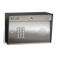
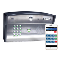
1.4 1808 Dimensions and Installation
1808 units can be mounted directly to a wall, pilaster, post mounted using a DoorKing mounting post (P/N 1200-045 or
1200-046). Be sure the unit is mounted securely and is not subject to vibration from closing doors or gates.
7.5”
11”
Side ViewBack View Front View
1808
1808 with Directory
7
8
9
4
5
6
1
2
3
0
P
ush Button
To Ca
ll
7
8
9
4
5
6
1
2
3
0
N
AM
E
Adams J
Bernard E
Brown
L
Davis
T
H
odges
S
Miller
J
Smith K
Thomas W
Zimme
r
R
1
9
5
2
4
6
8
3
7
CODE
7
8
9
4
5
6
1
2
3
0
NAME
Adams J
Bernard E
Brown L
Davis T
Hodges S
Miller J
Smith K
Thomas W
Zimmer R
1
9
5
2
4
6
8
3
7
CODE
Bottom View
.875” Dia
.875” Dia
5”
2.625”
3”
6.5”
4.75”
4.25”
6.75”
2.5”
2.5”
2.5”
2.5”
4.25”
Use existing 4 holes in cabinet
box to bolt the surface or wall
mount models on a DoorKing
mounting post. Use the
hardware that is supplied
with the mounting post.
Note: A gooseneck
mounting post anchored
in concrete does not
make a good ground.
Mount to a Mounting Post
Use the 4 existing holes in the cabinet box.
Run conduit inside or outside of wall or
pilaster if desired. Use appropriate
hardware to mount the cabinet (Not
supplied). Be sure that the mounting
hardware does not protrude into the
cabinet where it could cause a short.
Mount Directly to
a Wall or Pilaster
Plastic screw
anchors for
masonry if
required.
(Not supplied)
Conduit shown inside wall
Enclo
su
re
Enclosure
Installation
1. Route all wiring through conduit or
mounting post (not supplied).
2. Clean out the enclosure. Make sure that all
dirt, metal and/or wood debris is removed.
4. Re-install components back into the
enclosure (Reverse section 1.1.1). Use the
wiring schematics in the back of this manual
to help re-install the components if needed.
DO NOT apply any power at this time.
WARNING! If this entry
system is used to control a
vehicular gate with an
automatic gate operator, the
entry system must be
mounted a minimum of six
(6) feet away from the gate
and gate operator, or in
such a way that a person
cannot operate the entry
system and touch the gate
or gate operator at the same
time.