16
1800-060 Issued 7-19
Version A
1.6 Postal Lock Installation
At some locations, such as gated communities, it will be necessary to provide access to the mail carrier so that they can
deliver the mail. Mail carrier access will be provided by the installation of an Arrow Postal Lock. This is the same lock that the
Post Office uses for gang mailboxes. These locks are not available to the public. The installer or the building owner/manager
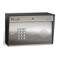
will have to call the Post Office and arrange for the installation of this lock into the telephone entry system. DoorKing 1803 &
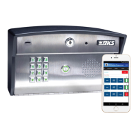
1810 telephone entry systems are designed to accept installation of the postal lock. If you are using the 1808 and need postal
service access, use the DoorKing Postal Lock Box sold separately (P/N 1402-080).
Prior to installation of the postal lock, be sure power to the telephone entry system is turned OFF.
1. Remove the hole plug on the faceplate of the telephone entry system.
2. Cut the wire tie wrapped around the switch ONLY when installing postal lock.
3. Remove the two hex nuts from the postal lock-mounting studs. Mount postal lock on the studs and secure with the hex nuts.
When the lock is installed, the pawl of the lock, in the extended position is depressing the switch. When the mail carrier inserts
his key and turns the postal lock, the pawl is withdrawn into the lock and the switch will activate the relay for the programmed
strike time, that has been programmed for this feature.
Factory default settings for the Postal Lock Switch: After the key has been turned, Relay 1 will activate (section 3.1.7) for One
(1) second of strike time (section 3.1.3).
Note: The switch input feature (section 3.1.7) is factory set to “activate a relay” and not “dial a phone number”.
Existing postal lock-mounting studs
located inside the faceplate
o
f
the 1803 & 1
8
10.
Existin
g
postal
lock-mounting n
u
t
s.
Factory w
ired
1803 & 1810
P
ostal Lock
Switch or inside
Postal Lock Box sold
separately.
Com
NC
Com
NC
Extended Pawl
Withdrawn Pawl
Relay Activates
Blue Wire
N.C
.
White Wire
Com
Pawl
POST
AL
LO
CK BOX
7
8
9
4
5
6
1
2
3
0
1
2
3
N
A
M
E
J
one
s
G
34
1
8
79
55
7
03
2
41
9
N
a
bur
J
N
e
u
m
a
nn
J
N
ix
on R
P
a
tt
e
r
s
o
n
F
P
e
r
e
z
F
P
e
t
r
o
lli
A
R
a
y
J
640
447
0
06
7
4
5
546
501
3
30
211
543
9
87
352
S
t
ol
l
a
c
h
H
S
y
nfol
A
T
o
m
l
i
ns
o
n
L
T
om
p
s
o
n
A
T
om
p
s
on S
T
y
l
e
r
Q
Wa
s
hi
ngt
o
n
G
Wa
s
hing
to
n
K
We
nt
L
W
hi
ting
M
W
i
n
s
t
o
n
F
W
y
a
t
t
J
650
7
91
0
21
076
1
0
0
3
3
4
213
229
00
7
134
60
9
3
89
6
79
211
670
4
4
1
T
ELE
PHONE ENTR
Y SYSTEM
M
ODEL
1803
O
PE
R
AT
IN
G
IN
ST
R
U
CTIO
NS
Lo
c
a
te
C
ode
N
u
m
be
r
o
n
D
i
r
ec
t
o
ry
.
P
ress
Co
de
N
u
m
ber
.
If
L
i
ne
i
s
B
u
s
y,
P
re
s
s
“
#
”
to
H
ang
U
P
.
T
ry Aga
in.
En
t
er
on
To
ne
.
1.
2.
3.
7
8
9
4
5
6
1
2
3
0
1803
Hole Plug
1810
Hole Plug
1808
POSTAL
LOCK BOX
7
8
9
4
5
6
1
2
3
0
Push B
utto
n
T
o C
al
l