Power Train Disassembly & Assembly
4. Measure the distance X or Y again. Compare the
dimension with the distance X or Y measured in
step 2. The difference between the two dimensions
is the amount the bearing caps have expanded
(leg spread).
Example
•
Distance X or Y
– Before tightening adjusting rings = 13.927 inch
(353.740 mm).
•
Distance X or Y
– After tightening adjusting rings = 13.936 inch
(353.970 mm)
•
13.936 inch – 13.927 inch = 0.009 inch (0.230 mm)
difference.
If the dimension is within speciffications, continue by
inspecting runout of the ring gear. If the dimension is
less than specifications, repeat steps 3 and 4 as
needed.
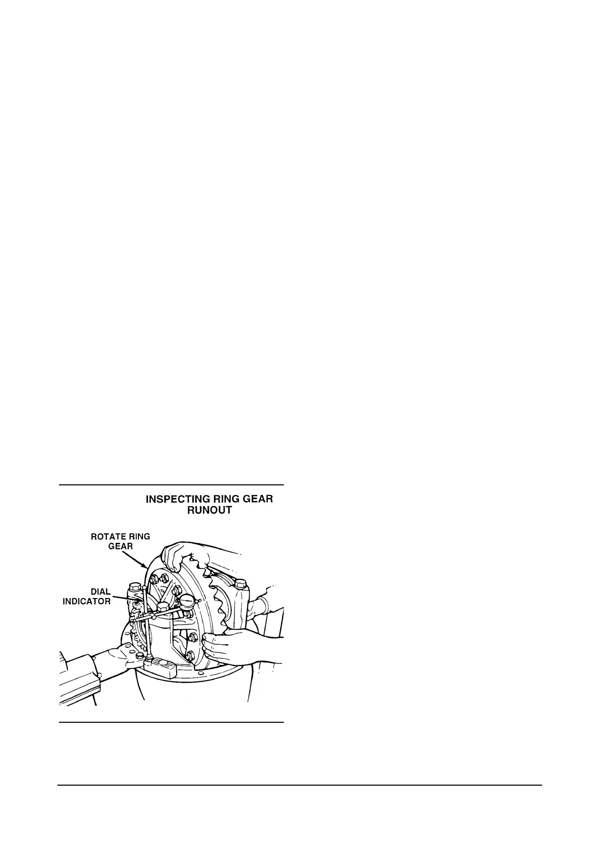
Checking the Runout of the
Ring Gear
Runout Specification
•
0.008 inch (0.200 mm)
1. Attach a dial indicator on the mounting flange of
the carrier.
2. Adjust the dial indicator so that the plunger or
pointer is against the back surface of the ring gear.
3. Set the dial indicator to zero (0).
4. Rotate the differential and ring gear and read the
dial indicator. The runout of the ring gear must not
exceed 0.008 inch (0.200 mm).
If runout of the ring gear exceeds this
specification, remove the differential and ring gear
assembly from the carrier. Refer to and preform
the disassembly procedure on page 11 and then
the following steps 5 and 6.
5. Inspect the differential parts including the carrier
for the problem that causes the runout of gear to
exceed specifications. Always replace defective
parts.
6. After the parts are repaired or replaced, install the
differential and ring gear into the carrier. Refer to
the procedure on page 32.
7. Repeat the procedure for preload adjustment of
differential bearings.
Ring Gear Backlash Adjustment
Specifications
– Range of backlash setting: 0.008 to 0.018 inch
(0.200-0.460 mm).
– Backlash setting for new gear sets: 0.012 inch
(0.300 mm)
If the old gear set is installed, adjust the backlash to
the setting that was measured before the carrier was
disassembled.
If a new gear set is installed, adjust the ring gear
backlash to the correct specification for a new gear
set.
After inspecting the tooth contact patterns, the
backlash can be adjusted within specification limits, if
needed. To change the location of the pattern use the
following procedures.
36