G643(E) Service Manual Chapter 6. LPG FUEL DELIVERY SYSTEM 197
Removal and Installation of CA100 Mixer for
G643E
Follow the procedures below for removal and
reinstallation of the CA100 mixer.
CA100 Certified Mixer Removal Steps
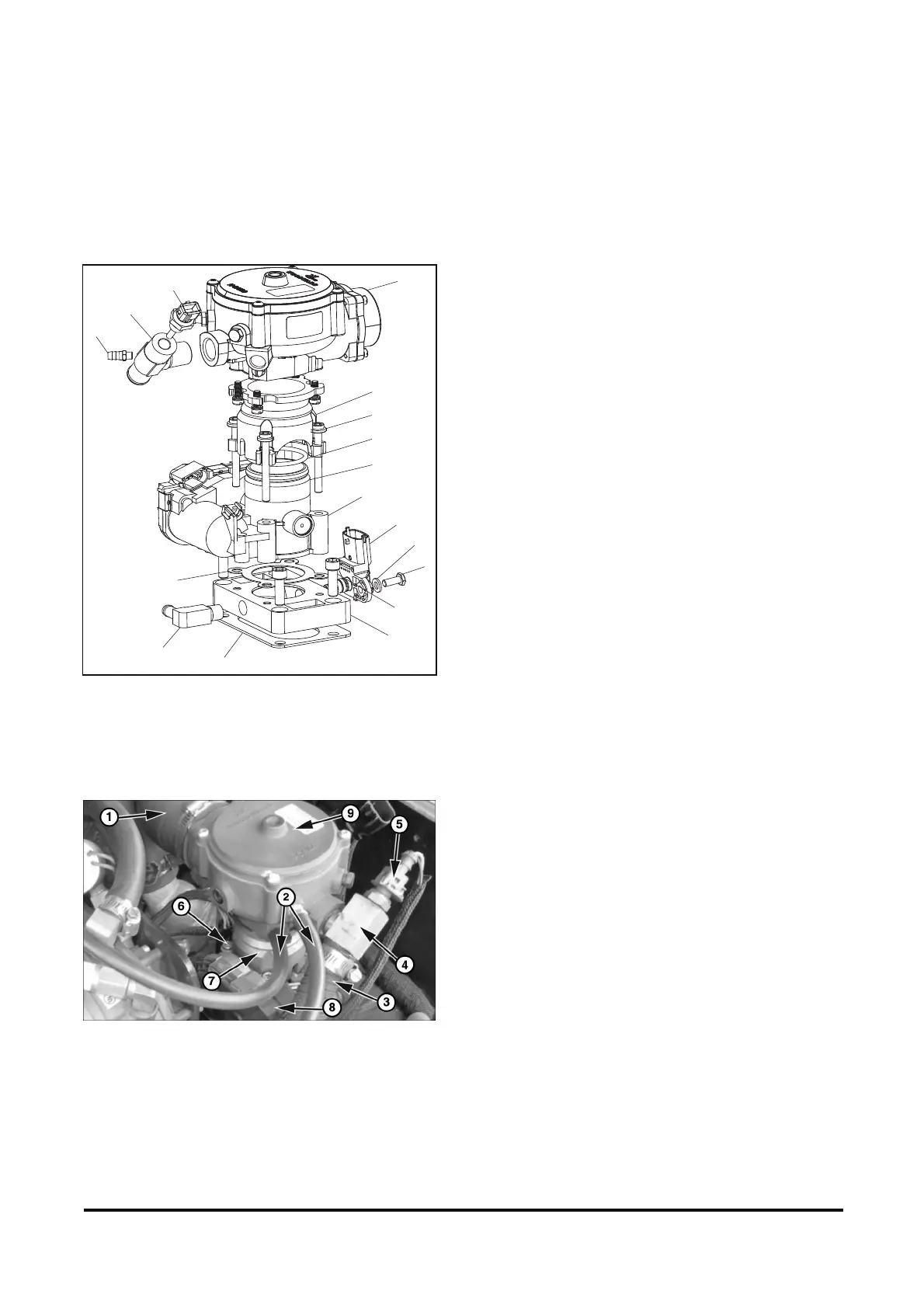
1. Gasket 2. Adapter 3. Fitting
4. Tmap 5. Washer 6. Bolt
7. Bolt 8. Gasket-ITB 9. ITB
10. O-Ring 11. O-Ring 12. Mixer
13. Adapter 14. Fuel Temp Sensor 15. Fitting
16. Apollo Adapter 17. Bolt
Figure 30. CA100 Mixer in Certified System
1. Close the liquid outlet valve in the forklift cylinder
or fuel storage container.
2. Purge the system of fuel by starting the engine
and running until all trapped fuel in the system is
exhausted and the engine shuts down.
3. Key switch in “OFF” position.
4. Remove the air cleaner hose (1).
5. Mark the two vacuum lines (2) to the mixer for
identification, as they must be reinstalled
correctly for proper operation. Remove the two
vacuum lines (2).
6. Remove vapor fuel inlet line (3) from the fuel
temperature sensor fitting (4).
7. Disconnect the fuel temperature sensor
connector (5).
8. Disconnect the wires leading to the electronic
throttle body by pinching the lock tabs on either
side of the wiring harness connector. (See Figure
31 for location of connector)
9. Loosen the four bolts (6) that secure the
mixer/adapter/throttle body assembly to the
intake manifold.
10. Remove the mixer (9), the adapter (7), and the
throttle body (8) as an assembly by gently pulling
upwards. Take care not to drop anything down
the intake manifold.
11. Gently wiggle and pull to separate mixer and
adapter from the throttle body. Take note of the
adapter orientation on the mixer, as it must be
reinstalled correctly for proper fit on the throttle.
12. Remove the four mounting screws that attach the
throttle body adapter to the mixer.
13. Remove the fuel temperature sensor (not shown)
from the tee (4).
14. Remove the fuel temperature sensor fitting
from the mixer. Take note of the fitting’s
orientation on the mixer, as it must be
reinstalled correctly for proper fit.
15. Remove the short vacuum port barb from the
mixer. (See Figure 32 for location of port barb
on mixer.)
14
13
15
8
3
1
12
16
17
10
11
9
4
5
6
7
2