G643 (E) Service Manual Chapter 3. Engine Mechanical System 78
Piston Selection
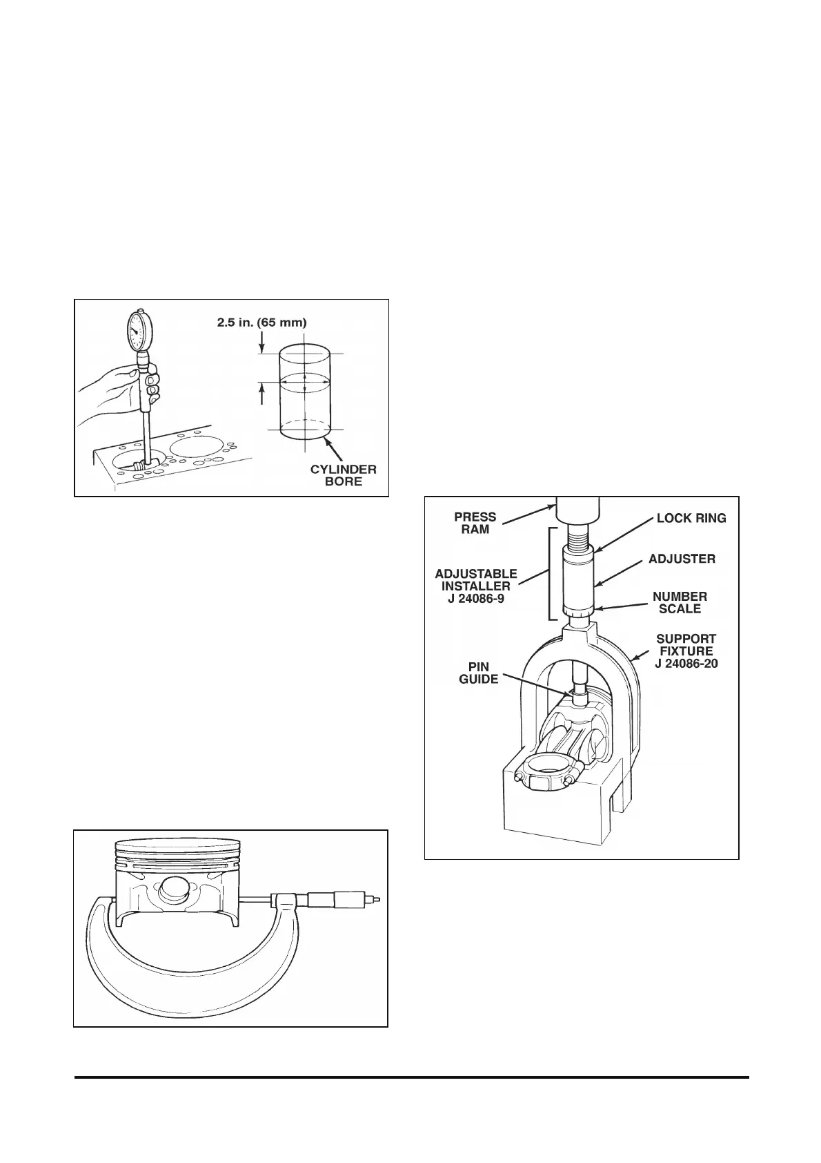
Figures 12-34 and 12-35
1. Check the used piston to cylinder bore clearance.
Measure
A. Cylinder bore diameter. Use a telescoping
bore gage, located 65 mm (2.5 in.) below the
top of the cylinder bore (figure 12-34).
Figure 12-34 Measuring Cylinder Bore Diameter
B. Piston diameter. Measure the piston skirt at a
right angle to the piston pin, at the centerline
of the piston pin (figure 12-35).
C. Subtract the piston diameter from the cylinder
bore diameter to determine piston to bore
clearance.
D. Refer to “Specifications” in the proper Section.
Determine if the piston clearance is in the
acceptable range.
2. If the used piston is not acceptable, determine if
a new piston will fit the cylinder bore.
3. If a new piston does not bring the clearance
within tolerances, the cylinder bore must be
reconditioned.
4. Mark the piston to identify the cylinder for which
it was fitted.
Figure 12-35 Measuring Piston Skirt
Piston Assembly
Assembling the Piston and Connecting Rod
Figure 12-36
Tool Required:
J 24086-B Piston Pin Remover and Installer Set
Install or Connect
1. Piston and connecting rod.
A. The valve cutouts in the piston crown must be
opposite the connecting rod bearing tangs.
B. Lubricate the piston pin holes in the piston
and connecting rod with engine oil.
C. Install the pin guide to hold the piston and
connecting rod together. Be sure to use the
proper pin guide. Refer to the instructions
supplied with the tool.
Figure 12-36 Installing Piston Pin
2. Piston pin.
A. Insert the piston pin into the piston pin hole.
B. Place the assembly on the support fixture.