G643 (E) Service Manual Chapter 3. Engine Mechanical System 66
4. Remove head gasket.
Torsional Damper Removal
Figure 12-9
Remove or Disconnect
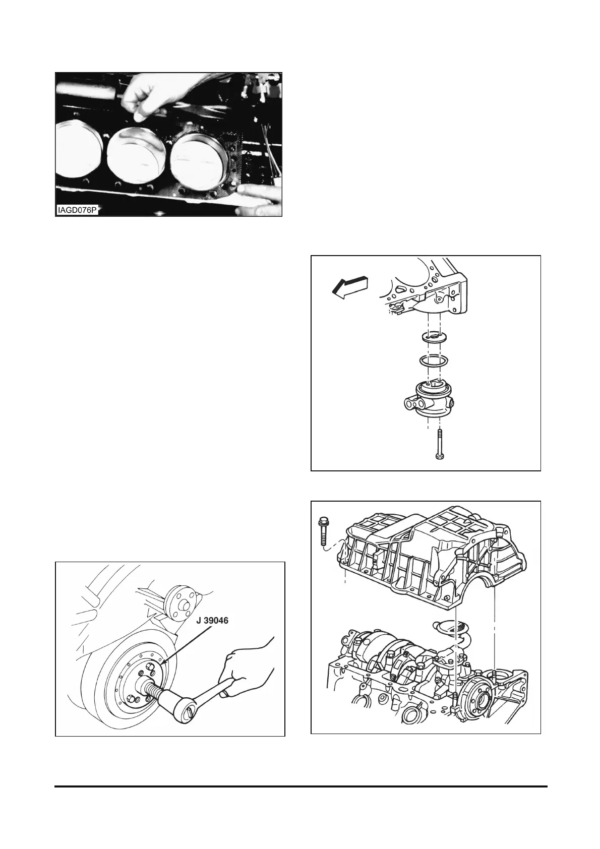
Tool Required:
J 39046 Torsional Damper Puller and Installer
NOTICE: The inertial weight section of the torsional
damper is assembled to the hub with a rubber
sleeve. The removal procedures must be followed
(with the proper tools) or movement of the inertia
weight section of the hub will destroy the tuning of
the torsional damper and the engine timing
reference.
1. Torsional damper bolt.
2. Torsional damper using J 39046 (figure 12-12).
3. Crankshaft key.
Figure 12-9 Removing Torsional Damper
Oil Pan Removal
Figures 12-10 and 12-11
Remove or Disconnect
1. Oil filter adapter bolts.
2. Oil filter adapter gasket.
3. Oil filter adapter O-ring seal, if equipped.
4. Oil filter adapter.
5. Oil pan nuts.
6. Oil pan bolts.
7. Oil pan.
8. Gasket.
Figure 12-10 Oil Filter Adapter Equipped with Oil Cooler (Typical)
Figure 12-11 Oil Pan