G643 (E) Service Manual Chapter 3. Engine Mechanical System 85
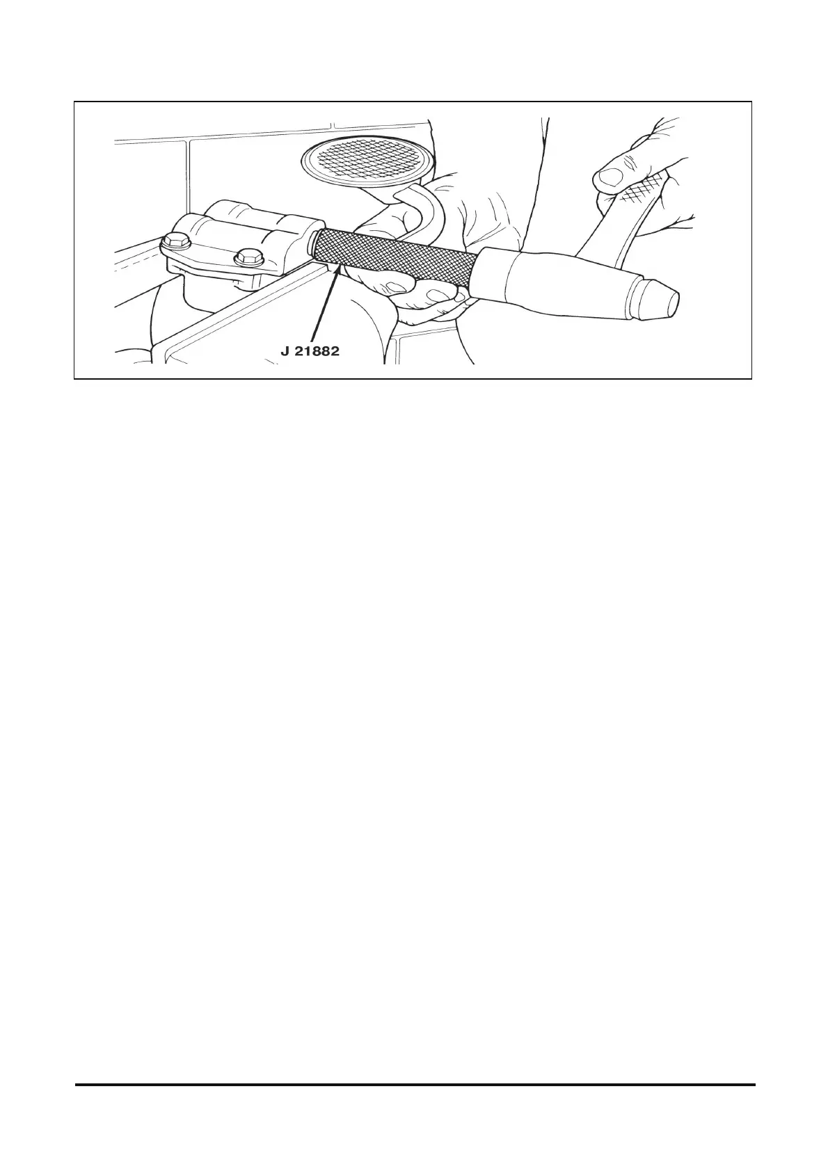
Figure 12-47 Installing Oil Pump Screen
Inspect
• With the shaft extension installed on the pump,
turn the drive shaft by hand to check for smooth
operation.
NOTICE: Be careful of twisting, shearing, or
collapsing the pipe when installing it to the pump. A
damaged pipe can cause lack of lubrication and
engine failure.
8. Pickup screen and pipe.
A. If the pickup screen and pipe assembly was
removed, it should be replaced with a new
part. Loss of press fit condition could result in
an air leak and loss of oil pressure.
B. Mount the oil pump in a soft-jawed vise.
C. Apply sealer to the end of the pipe.
D. Tap the pickup screen and pipe into place,
using J 21882 and a hammer.
E. The pump screen must be parallel with the
bottom of the oil pan when installed.
9. Oil pump drive shaft and connector.
Valve Train Components
IMPORTANT: Store all reusable components in
an exact order, so they may be reassembled in
the same position from which they were
removed.
Clean
• All parts in clean solvent and dry them with
compressed air.
• Make sure the oil passages through the pushrods
are clear.
Inspect
• Valve rocker arms and balls at their mating
surfaces. These surfaces should be free from
wear or damage.
• Valve rocker arm areas that contact the valve
stems and the socket areas that contact the ends
of the pushrods. These areas should be free of
wear or damage.
• Valve rocker arm nuts.
• Valve pushrod ends for scoring, roughness, or
bends.
- Roll the pushrod on a flat surface to determine
its straightness. If the rod is bent, the rod will
not roll freely. Replace if necessary.