G643 (E) Service Manual Chapter 3. Engine Mechanical System 69
Figure 12-15 Balance Shaft and Components
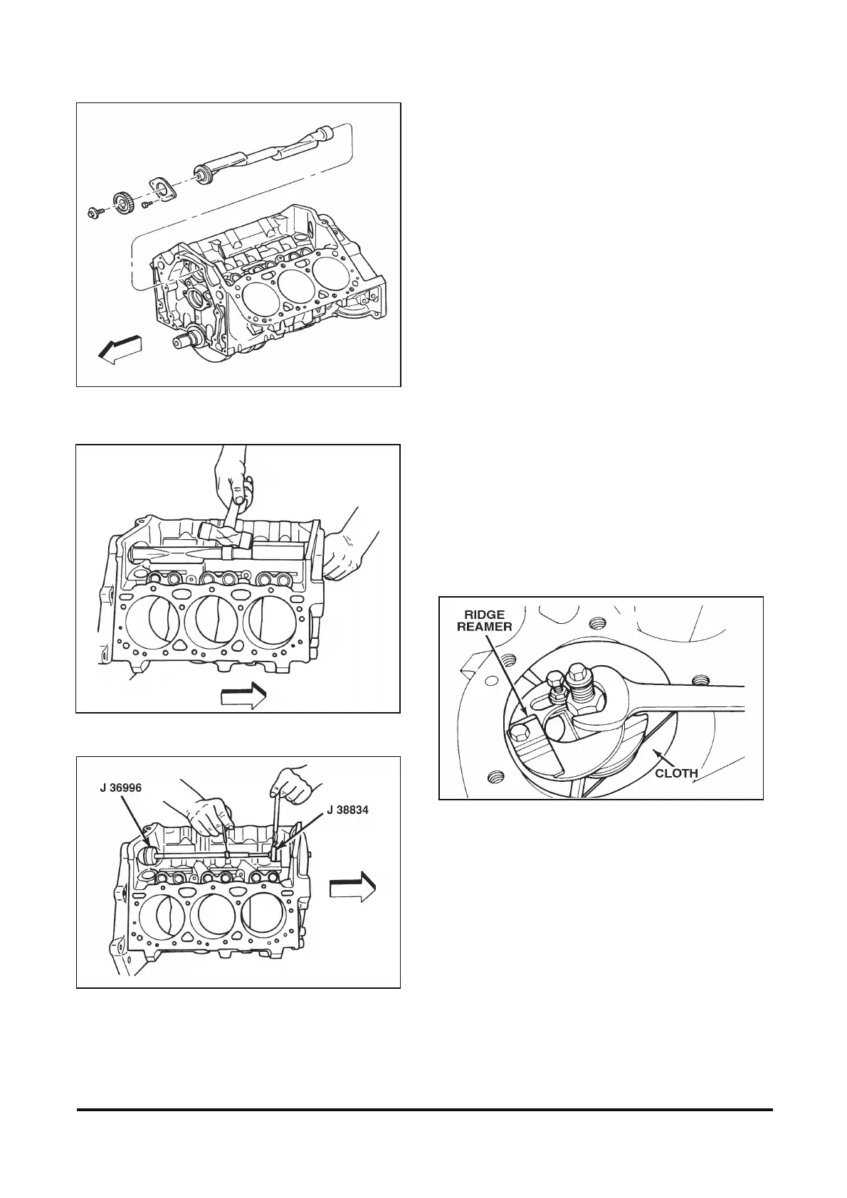
Figure 12-16 Removing Balance Shaft
Figure 12-17 Removing Balance Shaft Rear Bearing
IMPORTANT: The balance shaft with front
bearing are serviced as an assembly. Use only
the correct tools for bearing and shaft
installation. Inspect the balance shaft driven
gear and the drive gear for nicks and burrs.
Piston and Connecting Rod Removal
Figures 12-18 and 12-19
Tools Required:
J 24270 Ridge Reamer
J 5239 Guide Set
Remove or Disconnect
1. Ridge or deposits from the upper end of the
cylinder bores as follows:
A. Rotate the crankshaft until the piston is at
BDC.
B. Place a cloth on top of the piston.
Figure 12-18 Removing Cylinder Ridge
C. Perform the cutting operation with J 24270
(figure 12-18).
D. Rotate the crankshaft until the piston is at
TDC.
E. Remove the cloth and cuttings.
F. Repeat this procedure for each piston.
2. Mark the cylinder numbers on the tops of each
piston.