dormakaba 9000 Series MLR Installation Instructions
95071186 01-2021Exit Device
4
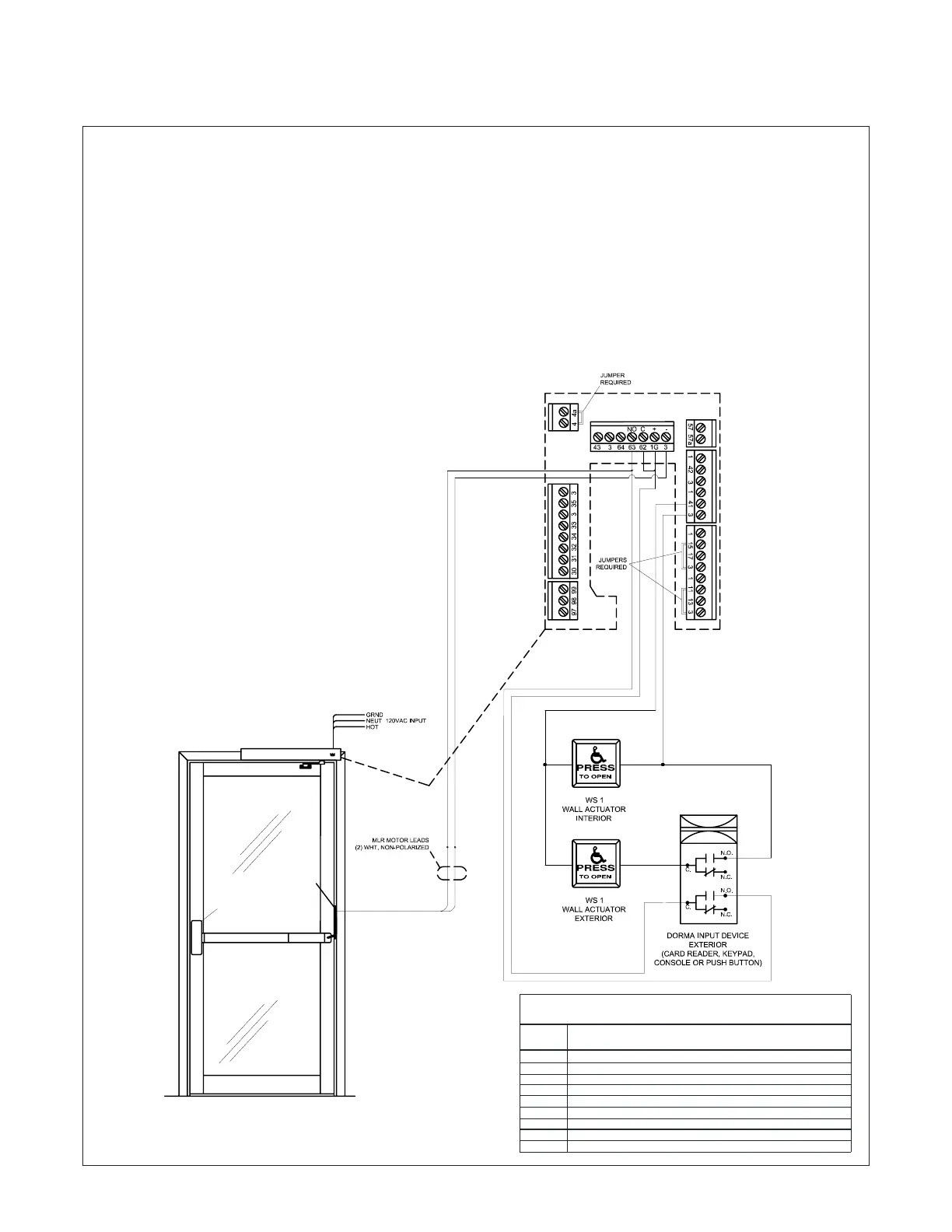
MLR x Hardwired Actuator x Input Device
. ED Low Energy Operator Single Door
Motorized Latch Retraction x Hard Wired Actuators x Input Device
OPERATION:
Door is locked and secure. Authorized entrance by presenting valid credentials at exterior input device which trigger the low energy
operator to retract the latch bolt of the 9000 MLR exit device, and enables the exterior WS-1 wall actuator. Pedestrian then has option of
automatic entrance by depressing the exterior WS-1 which triggers the low energy operator to open the door or manual entrance by exterior trim.
Authorized entrance also possible by key unlocking exterior trim to retract latch bolt of 9000 MLR exit device by-passing motorized latch retraction.
Egress by depressing interior WS-1 signals operator to retract latch bolt of 9000 MLR exit device. After delay time (set in field) the low energy operator
opens the door. Manual egress is always possible by depressing the touch bar of the 9000 MLR exit device.
LOSS OF POWER: ED low energy operator and 9000 MLR exit device are de-energized. Latch bolt of 9000 MLR exit device is released and ED low
energy operator allows door to close providing positive latching. Immediate egress is possible by depressing the touch bar of the 9000 MLR exit device.
NOTES: 1) All wiring and interface between EAC components and ED low energy operator to be determined and supplied by others.
2) All settings for ED low energy operator to be determined and set in field by others.
PARTS LIST:
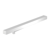
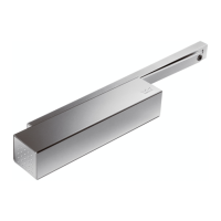
1 EA. - ED J8 Low Energy Operator: 115 VAC +/- 10% 50/60 Hz, 6.6 Amp max. (DORMAKABA) 2 EA. - WS-1 Wall Actuator (DORMAKABA)
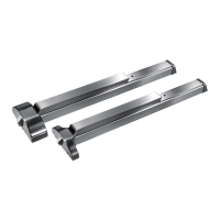
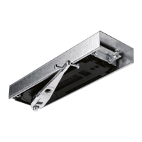
1 EA. - 9000 MLR Exit Device, .88 Amp @ 24VDC x Exterior trim (DORMAKABA) 1 EA. - Input Device (DORMAKABA)
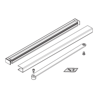
1 EA. - ES105 Power conduit (DORMAKABA)
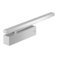
Low Energy Operator
9000 MLR EXIT DEVICE
EXTERIOR
TRIM
ES105 POWER
TRANSFER
ED OPERATOR
CONNECTION TERMINALS
AMPS 25 50 75 100 150 200 250 300
MINIMUM WIRE GUAGE CHART (AWG) FOR 24V AC/DC
DISTANCE IN FEET FOR 2 CONDUCTORS
.25
.50
.75
1.00
1.50
2.00
2.50
3.00
18 18 18 18 18 18 18 18
18 18 18 18 18 18 18 16
18 18 18 18 18 16 16 14
18 18 18 18 16 16 14 14
18 18 18 16 16 14
18 18 16 16 14
18 18 16 14
18 16 14 14
NOTE: This wiring diagram is provided to assist in interfacing
dormakaba products into the system described above.
Compatibility and functionality of components not supplied by
dormakaba are not guaranteed. Component failure resulting from
improper wiring is not covered by warranty. Refer to individual
device product information sheets and installation instructions
for wire guage sizes and additionalinformation.