dormakaba 9000 Series MLR Installation Instructions
95071186
01-2021Exit Device
7
Field Troubleshooting Guide
. Field troubleshooting guide (continued)
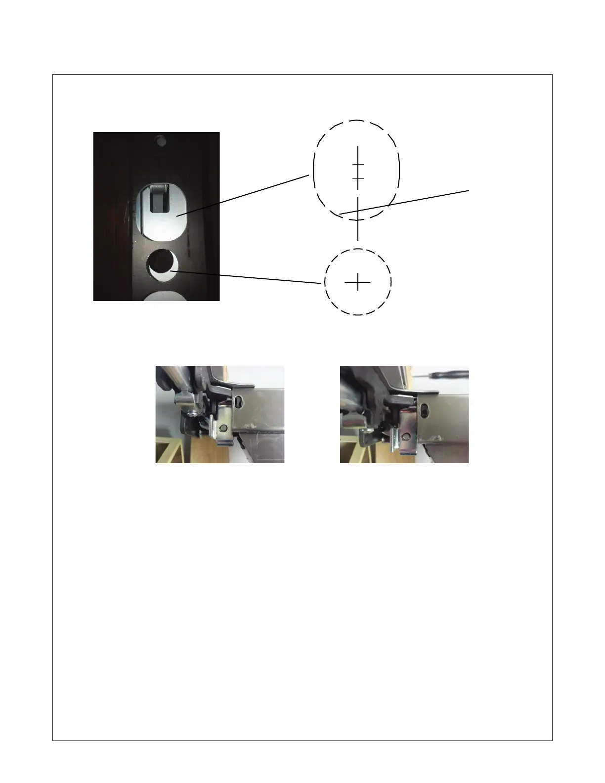
Check to ensure door is prepared correctly
to allow clearance for spindle and acutator
of trim to move freely.
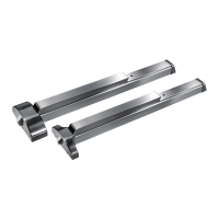
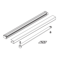
Touch bar and rail assembly should be installed to chassis using supplied screw located in chassis. Hole in chassis
should align with slotted hole in rail as show approximately centered. Rail does not set against rear of chassis.
The slotted hole should not be modified; This causes the nose of the touch bar to make contact with the bracket
located on the chassis which in turn can cause it to bind, as well as mess up the timing of the moving parts. It
may also cause malfunction of the outside trim assembly by putting it in a bind. Tighten screws until they make
contact with rail surface do not over tighten.
Touch bar and rail along with chassis should sit flush on the door; any warping or unlevelness may cause
bind issue with the motor assembly.
Read and follow all installation steps noted with in the standard installation manaul supplied with the device.
“The device must be installed properly and working properly mechanically prior to being energized electrically.”
The pages have been compiled from actual installation issues in the field. Their intent is to assist other installers.
G 1" Dia. thru for spindle clearance
H 1 1/2" Dia. x 1 3/4" High
outside face for cylinder
clearance. If actuator
has nylon sleeve installed;
additional material may be re-
quired to be removed at bottom.
G
H
Incorrect Correct