dormakaba 9000 Series MLR Installation Instructions
95071186 01-2021Exit Device
8
Field Troubleshooting Guide
. Field troubleshooting guide (continued)
There are two seperate factory settings for the MLR units; the 9300 & 9700 require a different stroke setting
than the 9400, 9800, 9100, 9600 or 9500. These are “preset at the factory”. The adjustment can be made in
the field as a last resort if for some reason it should be required. Follow the steps below, reverse steps to put
touch bar and rail back together after adjustments are made.
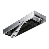
1. T ake the exit device off the door then remove the (6) screws attaching the Touch bar to the rail.
These (6) are in 2 triangular Patterns
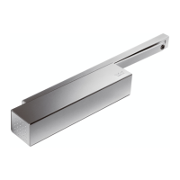
2. R emove the touch- bar from the rail assembly
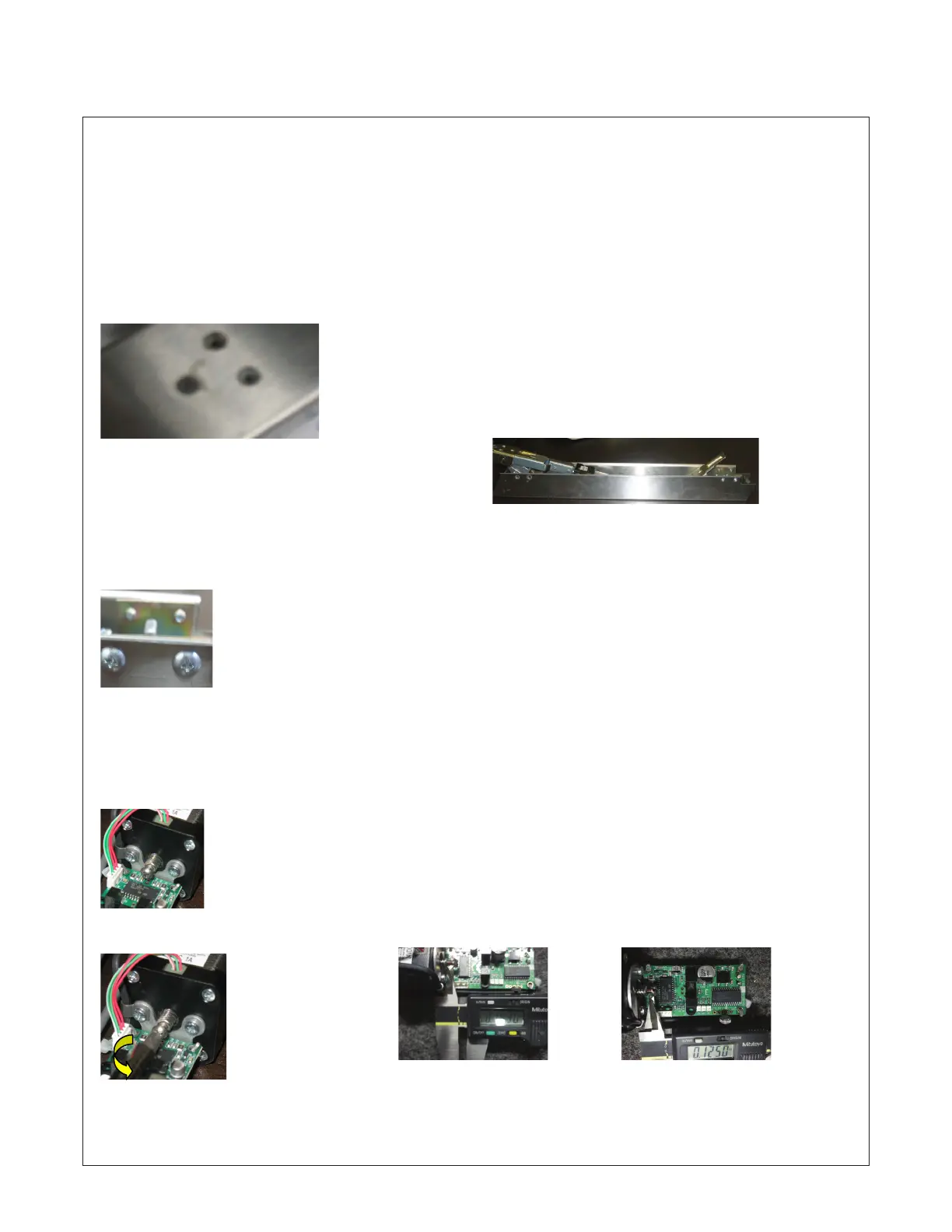
3. R emove the rear arm assembly from the touch-bar by removing 2 screws on each side of the
touch-bar.
4. P ull the rear arm assemble out of the touch-bar
5. O n the end of the black motor there is part of the worm gear sticking out of the motor. There is
an adjusting screw e xtends out of the worm gear.
6. U sing a Phillips screw driver turn the adjusting screw ¼ to 2 full revolutions counter clockwise.
Standard factory setting
for 9100,9600,9400,9800
or 9500 apx. 1/8” from front
edge of worm lead screw to
rear of adjusting screw.
Standard factory setting
for 9300 & 9700 is apx.
3/16” from front edge of
worm lead screw to rear
of adjusting screw.