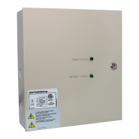
06-2023 dormakaba Canada Inc. RAC5 MFC Installation Guide – PK3738 | 10
4.1 Pre-installation Procedures
1. Identify a secure location for the RAC5 MFC enclosure.
• Access to the RAC5 MFC enclosure must be restricted to authorized personnel
• AC power must be available within distance specified in section 3.1.5.
• The location temperature must be from 0 to 49 °C (32 to 120 °F) and sheltered against weather
hazards and dripping water with relative humidity conditions less than 85% at 32 °C (90 °F)
• The enclosure must be installed using the hardware supplied
• The enclosure should be mounted at a workable height with clearance to completely open the
access door
• The enclosure can be placed either horizontally in the ceiling or vertically on a concrete, wood,
or plaster wall
2. Identify location(s) for contactless readers.
• Card readers must be placed within 1,000 feet (300 m) from the RAC5 MFC enclosure
• Readers should be installed in an obvious location at an ergonomic height near the access door
or elevator being controlled
• The space to use the contactless reader must be large enough to allow for adequate clearance
for the card being presented to the reader
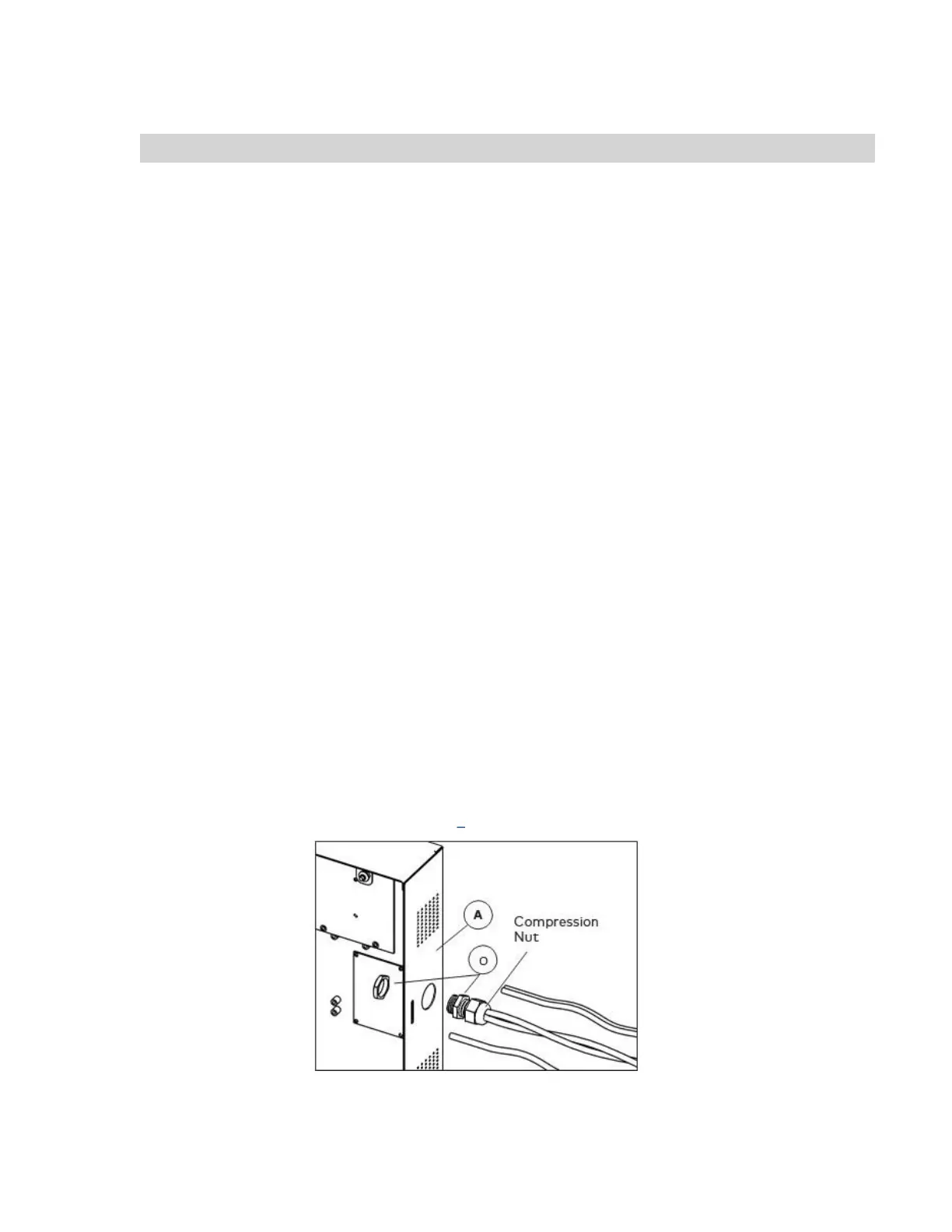
3. Install strain relief.
• Strain reliefs are provided in the hardware bag to secure the wires leading into the enclosure
and to help prevent the possibility of wire tampering
a) Determine the routing needed for all wiring of the RAC5 MFC card readers and
peripherals and select the enclosure knock-out(s) to be removed for installation of the
strain relief(s)
b) Remove the selected knock-out(s) using a hammer and screwdriver / awl, and from
the inner side of the enclosure, tap out the small metal disc
c) Based on the amount of wires to be routed, attach the appropriate strain relief to the
enclosure as shown in Figure 5. Do not attempt to route an excessive amount of wires.
If extra strain reliefs are required, please contact dormakaba Canada Inc
Figure 5 Strain Relief
4. Ensure that Dip Switch SW2 has Test Mode switch setting (SW2-4) set to OFF.